1GR-FE EMISSION CONTROL CANISTER ON-VEHICLE INSPECTION
PROCEDURE

 77740 1.INSPECT CHARCOAL CANISTER ASSEMBLY
Visually check the charcoal canister assembly for cracks or damage.
If cracks or damage is found, replace the charcoal canister assembly.
Check charcoal canister assembly operation under positive pressure.
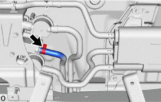
Disconnect the fuel hose from the fuel outlet valve assembly.
Close the fuel hose using a hose plug or a similar part.
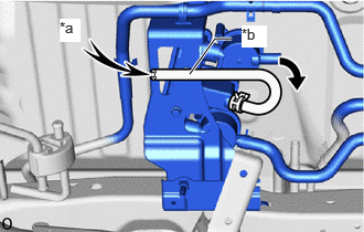
| *a | Air |
| *b | Test Hose |
Connect a test hose to the fuel outlet valve assembly.
Blow 8 kPa (0.1 kgf/cm2, 1.2 psi) of air into the test hose and check that air passes through the fuel outlet valve assembly.
- OK:
-
Air flow freely
If the result is not as specified, inspect the fuel outlet valve assembly and charcoal canister assembly.
Disconnect the test hose from the fuel outlet valve assembly.
Connect the fuel hose to the fuel outlet valve assembly.
Click hereEngine / Hybrid System>1GR-FE (EMISSION CONTROL)>CANISTER>INSTALLATION
Check charcoal canister assembly operation under vacuum.
Disconnect the fuel hose from the fuel outlet valve assembly.
Close the fuel hose using a hose plug or a similar part.
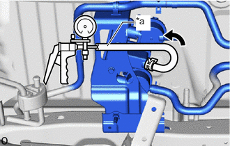
| *a | Test Hose |
Connect a test hose to the fuel outlet valve assembly.
Connect a vacuum pump to the test hose.
Using the vacuum pump, apply vacuum and check that the vacuum pump indicator does not move from its initial position.
- OK:
-
The indicator needle of the vacuum pump does not rise from its initial position.
- HINT:
-
The vacuum pump indicator may move when applying vacuum. If the vacuum pump indicator quickly returns to its initial position, the canister (charcoal canister assembly) is operating normally.
If the result is not as specified, inspect the fuel outlet valve assembly and charcoal canister assembly.
Disconnect the vacuum pump from the test hose.
Disconnect the test hose from the fuel outlet valve assembly.
Connect the fuel hose to the fuel outlet valve assembly.
Click hereEngine / Hybrid System>1GR-FE (EMISSION CONTROL)>CANISTER>INSTALLATION
Check for clogs in the air filter (when not using the GTS).
Disconnect the fuel hose from the fuel outlet valve assembly.
Close the fuel hose using a hose plug or a similar part.
| *a | Test Hose |
Connect a test hose to the fuel outlet valve assembly.
Connect a vacuum pump to the test hose.
Start the engine.
Warm up the engine.
Idle the engine for 15 minutes and check that the vacuum pump indicator does not move from its initial position.
- OK:
-
The indicator needle of the vacuum pump does not rise from its initial position.
- HINT:
-
The vacuum pump indicator may move when the purge VSV (No. 1 vacuum switching valve assembly) opens to vacuum. If the vacuum pump indicator quickly returns to its initial position, the canister (charcoal canister assembly) is operating normally.
Disconnect the vacuum pump from the test hose.
Disconnect the test hose from the fuel outlet valve assembly.
Connect the fuel hose to the fuel outlet valve assembly.
Click hereEngine / Hybrid System>1GR-FE (EMISSION CONTROL)>CANISTER>INSTALLATION
Check for clogs in the air filter (when using the GTS).
- HINT:
-
When performing an Active Test of the purge VSV (No. 1 vacuum switching valve assembly) using the GTS, it is not necessary to warm up and idle the engine for 15 minutes.
Disconnect the fuel hose from the fuel outlet valve assembly.
Close the fuel hose using a hose plug or a similar part.
| *a | Test Hose |
Connect a test hose to the fuel outlet valve assembly.
Connect a vacuum pump to the test hose.
Connect the GTS to the DLC3.
Start the engine.
Enter the following menus: Powertrain / Engine / Active Test / Activate the EVAP Purge VSV
- Powertrain > Engine > Active Test
-
Tester Display Activate the EVAP Purge VSV - 50004 372 1
- OK:
-
The indicator needle of the vacuum pump does not rise from its initial position.
- HINT:
-
·
When the engine idling, perform the Active Test.
·The vacuum pump indicator may move when the purge VSV (No. 1 vacuum switching valve assembly) opens to vacuum. If the vacuum pump indicator quickly returns to its initial position, the canister (charcoal canister assembly) is operating normally.
Disconnect the vacuum pump from the test hose.
Disconnect the test hose from the fuel outlet valve assembly.
Connect the fuel hose to the fuel outlet valve assembly.
Click hereEngine / Hybrid System>1GR-FE (EMISSION CONTROL)>CANISTER>INSTALLATION