Home › Drivetrain › DRIVE SHAFT / PROPELLER SHAFT › PROPELLER SHAFT ASSEMBLY › 2021.04–2021.07
RM38G0E _52 Drivetrain _101647 DRIVE SHAFT / PROPELLER SHAFT _0470833 PROPELLER SHAFT ASSEMBLY A

DRIVE SHAFT / PROPELLER SHAFT  PROPELLER SHAFT ASSEMBLY  DISASSEMBLY  


CAUTION / NOTICE / HINT
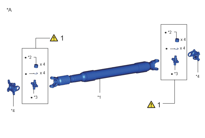
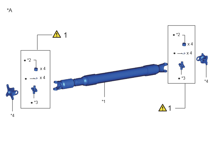
COMPONENTS (DISASSEMBLY)
C458703N01
0.771,1.688 1.677,3.625 0.906,1.938 5.625,0.854 6.531,2.792 0.906,1.938 1.25,1.688 1.25,1.333 1.25,1.333 1.75,1.333 false 5.688,3.615 6.104,3.615 6.104,3.615 6.104,2.781 false 3.49,3.24 3.49,2.74 false 1.177,3.271 1.177,3.104 false 6.115,2.448 6.115,2.281 false 0.469,3.719 0.469,3.302 false 6.917,2.531 6.917,2.115 false 1.26,2.25 1.26,2 1.26,2 1.177,2 false 6.167,1.365 6.167,1.115 6.167,1.115 6.083,1.115 false 5.948,1.708 6.115,1.708 false 1.021,2.573 1.188,2.573 false 2.104,1.177 2.385,1.531 0.281,0.354 18 false 1 5.49,3.51 5.771,3.865 0.281,0.354 18 false 1 1.396,2.156 1.854,2.354 0.458,0.198 10 false x 4 1.396,2.458 1.854,2.656 0.458,0.198 10 false x 4 6.313,1.292 6.771,1.49 0.458,0.198 10 false x 4 6.292,1.594 6.75,1.792 0.458,0.198 10 false x 4 3.406,3.313 3.719,3.51 0.313,0.198 10 false *1 5.75,1.042 6.146,1.271 0.396,0.229 10 false ● *2 0.854,1.917 1.25,2.146 0.396,0.229 10 false ● *2 0.865,2.49 1.021,2.688 0.156,0.198 10 false ● 5.781,1.604 5.938,1.802 0.156,0.198 10 false ● 1.063,3.313 1.448,3.563 0.385,0.25 10 false ● *3 5.969,2.49 6.375,2.75 0.406,0.26 10 false ● *3 6.844,2.583 7.156,2.781 0.313,0.198 10 false *4 0.229,0.24 0.594,0.635 0.365,0.396 12 false *A 0.385,3.781 0.698,3.979 0.313,0.198 10 false *4

Procedure Part Name Code
Z101186

Z101188

Z101187

1 REAR PROPELLER SHAFT UNIVERSAL JOINT SPIDER KIT 04371H (Click here) - -

*A for V35A-FTS - -
*1 PROPELLER SHAFT *2 SPIDER BEARING
*3 SPIDER *4 FLANGE YOKE
● Non-reusable part - -

C458704N02
0.698,1.688 1.677,3.625 0.979,1.938 5.625,0.854 6.531,2.792 0.906,1.938 1.25,1.667 1.25,1.167 1.25,1.167 1.75,1.167 false 5.865,3.625 6.198,3.625 6.198,3.625 6.198,2.792 false 3.5,3.25 3.5,2.75 false 1.135,3.292 1.135,3.125 false 6.073,2.5 6.073,2.333 false 0.417,3.729 0.417,3.313 false 6.906,2.594 6.906,2.177 false 1.208,2.26 1.208,2.01 1.208,2.01 1.125,2.01 false 6.188,1.427 6.188,1.177 6.188,1.177 6.104,1.177 false 5.938,1.792 6.104,1.792 false 1,2.635 1.167,2.635 false 2.125,1.021 2.406,1.375 0.281,0.354 18 false 1 5.615,3.469 5.896,3.823 0.281,0.354 18 false 1 1.344,2.208 1.802,2.406 0.458,0.198 10 false x 4 1.333,2.51 1.792,2.708 0.458,0.198 10 false x 4 6.281,1.385 6.74,1.583 0.458,0.198 10 false x 4 6.25,1.688 6.708,1.885 0.458,0.198 10 false x 4 3.406,3.313 3.719,3.51 0.313,0.198 10 false *1 5.781,1.073 6.177,1.302 0.396,0.229 10 false ● *2 0.792,1.927 1.188,2.156 0.396,0.229 10 false ● *2 0.823,2.542 0.979,2.74 0.156,0.198 10 false ● 5.802,1.688 5.958,1.885 0.156,0.198 10 false ● 1.021,3.344 1.365,3.625 0.344,0.281 10 false ● *3 5.958,2.531 6.417,2.771 0.458,0.24 10 false ● *3 6.844,2.635 7.156,2.833 0.313,0.198 10 false *4 0.229,0.24 0.594,0.635 0.365,0.396 12 false *A 0.354,3.781 0.667,3.979 0.313,0.198 10 false *4

Procedure Part Name Code
Z101186

Z101188

Z101187

1 REAR PROPELLER SHAFT UNIVERSAL JOINT SPIDER KIT 04371H (Click here) - -

*A for 1GR-FE - -
*1 PROPELLER SHAFT *2 SPIDER BEARING
*3 SPIDER *4 FLANGE YOKE
● Non-reusable part - -

NOTICE:
·

When using a vise, place aluminum plates between the part and vise.

·

When using a vise, do not overtighten it.


PROCEDURE

Hide 04371H 1.REMOVE REAR PROPELLER SHAFT UNIVERSAL JOINT SPIDER KIT

Z101186

HINT:

Use the same procedure for all universal joint spider assemblies.


a.
C458711C01
2.615,3.281 3.281,3.281 true 6.208,2.281 6.427,2.281 true 6.354,4.24 6.573,4.24 true 0.604,3.01 1.271,3.01 true 0.792,5.042 1.458,5.042 true 1.708,0.823 1.333,0.354 1.333,0.354 1.844,0.688 true 2.792,4.854 3.458,4.854 true 3.385,3.219 3.542,3.417 0.156,0.198 10 false A 6.042,2.208 6.198,2.406 0.156,0.198 10 false *d 6.167,4.156 6.323,4.354 0.156,0.198 10 false *d 0.271,2.958 0.625,3.188 0.354,0.229 10 false SST 0.49,4.979 0.844,5.208 0.354,0.229 10 false SST 1.604,3.333 1.76,3.531 0.156,0.198 10 false *b 1.146,0.229 1.302,0.427 0.156,0.198 10 false *a 1.938,4.469 2.094,4.667 0.156,0.198 10 false *b 0.99,4.344 1.146,4.542 0.156,0.198 10 false *c 0.521,0.156 0.802,0.51 0.281,0.354 18 false i 4.115,0.146 4.656,0.49 0.542,0.344 18 false ii, iii 0.49,2.167 1.031,2.51 0.542,0.344 18 false iv 4.104,2.156 4.646,2.5 0.542,0.344 18 false v, vi 0.49,3.948 1.229,4.292 0.74,0.344 18 false vii, viii 4.156,3.938 4.917,4.281 0.76,0.344 18 false ix, x 3.542,4.802 3.698,5 0.156,0.198 10 false A 0.802,2.344 0.958,2.542 0.156,0.198 10 false *c
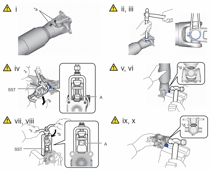
*a Matchmark *b Turn
*c Hold *d Hammering Point


i.

Place matchmarks on the flange yoke and propeller shaft.


ii.

Using a brass bar and hammer, slightly tap in the spider bearing outer races.


iii.

Using 2 screwdrivers, remove the 4 snap rings from the grooves.


iv.

Using SST, remove the spider bearing from the rear propeller shaft assembly.

SST
09332-25010  

HINT:

Before installing SST, sufficiently raise the part labeled A. If the part labeled A is too low, it may be difficult to install SST.


v.

Tap off the spider bearing with a hammer.

NOTICE:

Do not tap the shaft.


HINT:

Remove the spider bearing on the opposite side using the same procedure.


vi.

Remove the flange yoke from the rear propeller shaft assembly.


vii.

Install the 2 removed spider bearing outer races to the spider.


viii.

Using SST, remove the spider bearing from the flange yoke.

SST
09332-25010  

HINT:

Before installing SST, sufficiently raise the part labeled A. If the part labeled A is too low, it may be difficult to install SST.


ix.

Tap off the spider bearing with a hammer.


x.

Remove the spider.