Home › Drivetrain › AJA0F (AUTOMATIC TRANSMISSION / TRANSAXLE) › AUTOMATIC TRANSMISSION SYSTEM (for V35A-FTS)
RM38G0E _52 Drivetrain _100435 AJA0F AUTOMATIC TRANSMISSION / TRANSAXLE _0472752 AUTOMATIC TRANSMISSION SYSTEM(for V35A-FTS) J

AJA0F AUTOMATIC TRANSMISSION / TRANSAXLE  AUTOMATIC TRANSMISSION SYSTEM(for V35A-FTS)  TCM Power Source Circuit  


DESCRIPTION

When the ignition switch is turned to ON, battery voltage is applied to terminal MREL of the ECM through the coil of the EFI-MAIN NO. 1 relay. This causes the EFI-MAIN NO. 1 relay to close, which supplies power to terminal +B of the TCM.

WIRING DIAGRAM
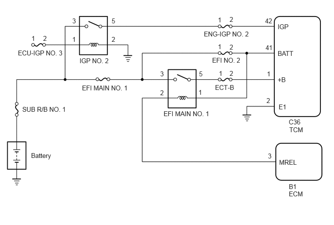
C458220E02
5.958,0.49 6.417,0.688 0.458,0.198 10 false IGP 5.958,1.063 6.573,1.26 0.615,0.198 10 false BATT 5.958,1.625 6.271,1.823 0.313,0.198 10 false +B 5.979,2.208 6.292,2.406 0.313,0.198 10 false E1 5.99,3.396 6.604,3.594 0.615,0.198 10 false MREL 5.75,3.26 5.906,3.458 0.156,0.198 10 false 3 5.719,2.073 5.875,2.271 0.156,0.198 10 false 2 5.729,1.5 5.885,1.698 0.156,0.198 10 false 1 5.698,0.938 6.01,1.135 0.313,0.198 10 false 41 5.688,0.365 6,0.563 0.313,0.198 10 false 42 4.615,1.792 5.385,1.99 0.771,0.198 10 false ECT-B 4.552,1.208 5.927,1.406 1.375,0.198 10 false EFI NO. 2 4.375,0.646 6.365,0.844 1.99,0.198 10 false ENG-IGP NO. 2 4.271,1.5 4.427,1.698 0.156,0.198 10 false 5 4.26,1.896 4.417,2.094 0.156,0.198 10 false 1 3.438,1.906 3.594,2.104 0.156,0.198 10 false 2 3.438,1.5 3.594,1.698 0.156,0.198 10 false 3 1.76,1.802 3.906,2 2.146,0.198 10 false EFI MAIN NO. 1 3.51,2.354 5.656,2.552 2.146,0.198 10 false EFI MAIN NO. 1 1.708,1.219 3.083,1.417 1.375,0.198 10 false IGP NO. 2 0.385,1.052 2.375,1.25 1.99,0.198 10 false ECU-IGP NO. 3 0.479,2.26 2.469,2.458 1.99,0.198 10 false SUB R/B NO. 1 0.667,3.25 1.438,3.448 0.771,0.198 10 false Battery 6.198,4.073 6.719,4.417 0.521,0.344 10 false ECM 6.198,3.917 6.51,4.115 0.313,0.198 10 false B1 6.208,2.698 6.615,3.01 0.406,0.313 10 false TCM 6.198,2.531 6.656,2.729 0.458,0.198 10 false C36 4.927,1.49 5.083,1.688 0.156,0.198 10 false 2 4.927,0.927 5.083,1.125 0.156,0.198 10 false 2 4.927,0.333 5.083,0.531 0.156,0.198 10 false 2 4.698,1.49 4.854,1.688 0.156,0.198 10 false 1 4.677,0.917 4.833,1.115 0.156,0.198 10 false 1 4.677,0.344 4.833,0.542 0.156,0.198 10 false 1 0.677,0.74 0.833,0.938 0.156,0.198 10 false 1 0.927,0.74 1.083,0.938 0.156,0.198 10 false 2 2.396,0.76 2.552,0.958 0.156,0.198 10 false 2 1.552,0.76 1.708,0.958 0.156,0.198 10 false 1 1.552,0.365 1.708,0.563 0.156,0.198 10 false 3 2.396,0.365 2.552,0.563 0.156,0.198 10 false 5

CAUTION / NOTICE / HINT

NOTICE:

Inspect the fuses for circuits related to this system before performing the following procedure.


PROCEDURE

1.CHECK HARNESS AND CONNECTOR (TCM - BODY GROUND)
a.

Disconnect the TCM connectors.


Result:
Proceed to
OK
NG


OK

2.CHECK HARNESS AND CONNECTOR (NO. 2 ENGINE ROOM RELAY BLOCK AND JUNCTION BLOCK ASSEMBLY - TCM)

NG

REPAIR OR REPLACE HARNESS OR CONNECTOR

2.CHECK HARNESS AND CONNECTOR (NO. 2 ENGINE ROOM RELAY BLOCK AND JUNCTION BLOCK ASSEMBLY - TCM)
a.

Remove the EFI MAIN NO. 1 relay, EFI NO. 2 fuse and ENG-IGP NO. 2 fuse from the No. 2 engine room relay block and junction block assembly.


b.

Disconnect the TCM connector.


c.

Measure the resistance according to the value(s) in the table below.

Standard Resistance:
Tester Connection Condition Specified Condition

Click Location & Routing(C36)Location & Routing

Click Connector(C36)Engine Compartment>Connecting Wire / Cooling Fan Wire / Engine Wire / Fuel Pump Motor Wire / No. 1 Connecting Wire / No. 10 Engine Wire / No. 2 Connecting Wire / No. 3 Connecting Wire / No. 4 Connecting Wire / Sensor Wire / Turbocharger Wire>Transmission Control ECU Assembly

5 (EFI MAIN NO. 1 relay) - C36-1 (+B) Always Below 1 Ω
2 (EFI NO. 2 fuse) - C36-41 (BATT) Always Below 1 Ω
2 (ENG-IGP NO. 2 fuse) - C36-42 (IGP) Always Below 1 Ω
5 (EFI MAIN NO. 1 relay) or C36-1 (+B) - Body ground and other terminals Always 10 kΩ or higher
2 (EFI NO. 2 fuse) or C36-41 (BATT) - Body ground and other terminals Always 10 kΩ or higher
2 (ENG-IGP NO. 2 fuse) or C36-42 (IGP) - Body ground and other terminals Always 10 kΩ or higher


Result:
Proceed to
OK
NG


OK

GO TO SFI SYSTEM (ECM POWER SOURCE CIRCUIT)

NG

REPAIR OR REPLACE HARNESS OR CONNECTOR