Home › Suspension › SUSPENSION CONTROL › ELECTRONIC-KINETIC DYNAMIC SUSPENSION SYSTEM
RM38G0E _53 Suspension _100546 SUSPENSION CONTROL _0470891 ELECTRONIC-KINETIC DYNAMIC SUSPENSION SYSTEM C

SUSPENSION CONTROL  ELECTRONIC-KINETIC DYNAMIC SUSPENSION SYSTEM  C183312  Fr Stabilizer Solenoid A Control Circuit Circuit Short to Battery  


DESCRIPTION

DTC No. Detection Item DTC Detection Condition Trouble Area DTC Output from
C183312 Fr Stabilizer Solenoid A Control Circuit Circuit Short to Battery Short circuit detected in solenoid valve
·

Front stabilizer housing sub-assembly

·

Harness or connector

·

Speed sensor RH (wire harness)

·

Stabilizer control ECU


Electronic-Kinetic Dynamic Suspension System (E-KDSS)

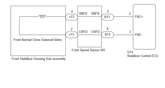
WIRING DIAGRAM

C458204E03
0.51,2.458 3.26,2.823 2.75,0.365 10 false Front Stabilizer Housing Sub-assembly 3,0.635 3.458,0.823 0.458,0.188 10 false z13 2.99,1.406 3.469,1.594 0.479,0.188 10 false z13 4.531,0.646 4.885,0.844 0.354,0.198 10 false B13 4.552,1.406 4.906,1.604 0.354,0.198 10 false B13 5.854,0.635 6.292,0.823 0.438,0.188 10 false FNC+ 5.854,1.417 6.292,1.604 0.438,0.188 10 false FNC- 3.083,0.417 3.24,0.615 0.156,0.198 10 false 4 3.073,1.177 3.229,1.375 0.156,0.198 10 false 2 4.646,0.406 4.802,0.604 0.156,0.198 10 false 2 4.635,1.156 4.792,1.354 0.156,0.198 10 false 8 5.604,0.51 5.76,0.708 0.156,0.198 10 false 2 5.604,1.292 5.76,1.49 0.156,0.198 10 false 3 3.115,2.083 4.719,2.281 1.604,0.198 10 false Front Speed Sensor RH 5.521,2.167 5.875,2.365 0.354,0.198 10 false Q14 5.521,2.333 7,2.531 1.479,0.198 10 false Stabilizer Control ECU 3.958,0.5 4.396,0.688 0.438,0.188 10 false SBFD 3.958,1.292 4.396,1.479 0.438,0.188 10 false CRFD 0.583,1.635 2.854,1.896 2.271,0.26 10 false Front Normal Close Solenoid Valve 3.427,0.5 3.865,0.688 0.438,0.188 10 false SBFD 3.427,1.292 3.865,1.479 0.438,0.188 10 false CRFD

PROCEDURE

1.CHECK HARNESS AND CONNECTOR (POWER SUPPLY - STABILIZER CONTROL ECU)
a.

Disconnect the Q14 stabilizer control ECU connector.


b.

Measure the voltage according to the value(s) in the table below.

Standard Voltage:
Tester Connection Condition Specified Condition

Click Location & Routing(Q14)Location & Routing

Click Connector(Q14)Body>Air Conditioning Wiring Harness Assembly / Floor Wire / Step Rear Floor Wire RH / Theft Warning Sensor Cord Sub-Assembly>Stabilizer Control ECU

Q14-2 (FNC+) - Body ground Always Below 1 V
Q14-3 (FNC-) - Body ground Always Below 1 V


c.

Connect the Q14 stabilizer control ECU connector.


Result:
Proceed to
OK
NG


OK

2.CHECK HARNESS AND CONNECTOR (STABILIZER CONTROL ECU - BODY GROUND)

NG

REPAIR OR REPLACE HARNESS OR CONNECTOR

2.CHECK HARNESS AND CONNECTOR (STABILIZER CONTROL ECU - BODY GROUND)
a.

Disconnect the Q14 stabilizer control ECU connector.


b.

Measure the resistance according to the value(s) in the table below.

Standard Resistance:
Tester Connection Condition Specified Condition

Click Location & Routing(Q14)Location & Routing

Click Connector(Q14)Body>Air Conditioning Wiring Harness Assembly / Floor Wire / Step Rear Floor Wire RH / Theft Warning Sensor Cord Sub-Assembly>Stabilizer Control ECU

Q14-2 (FNC+) - Body ground Always 10 kΩ or higher
Q14-3 (FNC-) - Body ground Always 10 kΩ or higher


c.

Connect the Q14 stabilizer control ECU connector.


Result:
Proceed to
OK
NG


OK

3.INSPECT FRONT STABILIZER HOUSING SUB-ASSEMBLY (FRONT NORMAL CLOSE SOLENOID VALVE)

NG

4.CHECK HARNESS AND CONNECTOR (FRONT SPEED SENSOR RH - BODY GROUND)
3.INSPECT FRONT STABILIZER HOUSING SUB-ASSEMBLY (FRONT NORMAL CLOSE SOLENOID VALVE)
a.
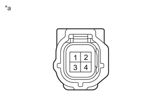
C457010C02
0.104,0.083 0.417,0.24 0.313,0.156 10 false *a
*a Component without harness connected
(Front Stabilizer Housing Sub-assembly)


Disconnect the z13 front stabilizer housing sub-assembly connector.


b.

Measure the resistance according to the value(s) in the table below.

Standard Resistance:
Tester Connection Condition Specified Condition
2 - 4 25°C (77°F) 4.58 to 5.02 Ω


c.

Connect the z13 front stabilizer housing sub-assembly connector.


Result:
Proceed to
OK
NG


OK

REPLACE STABILIZER CONTROL ECU

NG

REPLACE FRONT STABILIZER HOUSING SUB-ASSEMBLY

4.CHECK HARNESS AND CONNECTOR (FRONT SPEED SENSOR RH - BODY GROUND)
a.
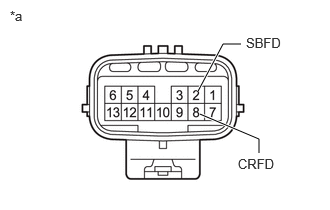
C457012C01
2.698,1.594 2.698,1.448 2.698,1.448 2.083,1.188 true 2.51,0.458 2.323,0.458 2.323,0.458 2.063,0.948 true 0.104,0.083 0.417,0.24 0.313,0.156 10 false *a 2.479,1.625 2.979,1.813 0.5,0.188 10 false CRFD 2.563,0.365 3.063,0.552 0.5,0.188 10 false SBFD
*a Component without harness connected
(Front Speed Sensor RH)


Disconnect the B13 front speed sensor RH connector.


b.

Measure the resistance according to the value(s) in the table below.

Standard Resistance:
Tester Connection Condition Specified Condition
2 (SBFD) - Body ground Always 10 kΩ or higher
8 (CRFD) - Body ground Always 10 kΩ or higher


c.

Connect the B13 front speed sensor RH connector.


Result:
Proceed to
OK
NG


OK

REPAIR OR REPLACE HARNESS OR CONNECTOR

NG

5.CHECK HARNESS AND CONNECTOR (FRONT STABILIZER HOUSING SUB-ASSEMBLY - BODY GROUND)
a.
C457010C02
0.104,0.083 0.417,0.24 0.313,0.156 10 false *a
*a Component without harness connected
(Front Stabilizer Housing Sub-assembly)


Disconnect the z13 front stabilizer housing sub-assembly connector.


b.

Measure the resistance according to the value(s) in the table below.

Standard Resistance:
Tester Connection Condition Specified Condition
2 - Body ground Always 10 kΩ or higher
4 - Body ground Always 10 kΩ or higher


c.

Connect the z13 front stabilizer housing sub-assembly connector.


Result:
Proceed to
OK
NG


OK

NG

REPLACE FRONT STABILIZER HOUSING SUB-ASSEMBLY