SUSPENSION CONTROL ELECTRONIC-KINETIC DYNAMIC SUSPENSION SYSTEM C183C14 Rr Stabilizer Solenoid B Control Circuit Circuit Short to Ground or Open
DESCRIPTION
| DTC No. | Detection Item | DTC Detection Condition | Trouble Area | DTC Output from |
|---|---|---|---|---|
| C183C14 | Rr Stabilizer Solenoid B Control Circuit Circuit Short to Ground or Open | Open circuit detected in solenoid valve |
·
Stabilizer control with accumulator housing assembly
·
Harness or connector
·
Stabilizer control ECU |
Electronic-Kinetic Dynamic Suspension System (E-KDSS) |
WIRING DIAGRAM
Refer to C183C12.
Click hereSuspension>SUSPENSION CONTROL>ELECTRONIC-KINETIC DYNAMIC SUSPENSION SYSTEM>C183C12
PROCEDURE
Disconnect the Q13 stabilizer control ECU connector.
Disconnect the vV1 stabilizer control with accumulator housing assembly connector.
Measure the resistance according to the value(s) in the table below.
- Standard Resistance:
-
Tester Connection Condition Specified Condition Click Location & Routing(Q13,vV1)Location & Routingewd_type=routing;type=c,w;code=Q13,vV1
Click Connector(vV1)Body>Stabilizer Control Wire>Stabilizer Control Wire and Frame Wireewd_type=component;type=w;code=vV1;pinno=3,4
Q13-2 (RLO+) - vV1-3 Always Below 1 Ω Q13-1 (RLO-) - vV1-4 Always Below 1 Ω Q13-2 (RLO+) or vV1-3 - Body ground Always 10 kΩ or higher Q13-1 (RLO-) or vV1-4 - Body ground Always 10 kΩ or higher
Connect the vV1 stabilizer control with accumulator housing assembly connector.
Connect the Q13 stabilizer control ECU connector.
- Result:
-
Proceed to OK NG
OK
NG
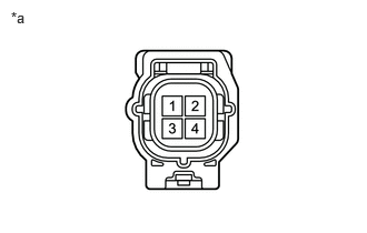
| *a | Component without harness connected (Stabilizer Control with Accumulator Housing Assembly) |
Disconnect the vV1 stabilizer control with accumulator housing assembly connector.
Measure the resistance according to the value(s) in the table below.
- Standard Resistance:
-
Tester Connection Condition Specified Condition 3 - 4 25°C (77°F) 4.58 to 5.02 Ω
Connect the vV1 stabilizer control with accumulator housing assembly connector.
- Result:
-
Proceed to OK NG
OK
NG