RM38G0E _51 Engine / Hybrid System _101531 1GR-FE EMISSION CONTROL _0474411 AIR FILTER A
1GR-FE EMISSION CONTROL AIR FILTER INSTALLATION
CAUTION / NOTICE / HINT
COMPONENTS (INSTALLATION)
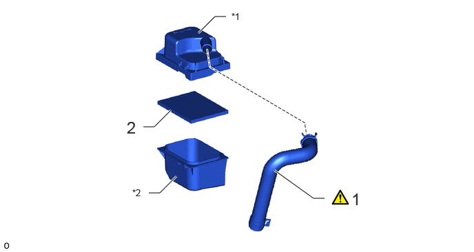
2.167,1.917 2.333,1.917 2.333,1.917 2.583,1.667 true 4.146,2.573 4.74,3 4.74,3 4.906,3 true 3,0.5 3.25,0.25 3.25,0.25 3.417,0.25 true 2.25,2.917 2.417,2.917 2.417,2.917 2.667,2.667 true 1.917,1.781 2.083,2.031 0.167,0.25 18 false 2 5.313,2.865 5.927,3.115 0.615,0.25 18 false 1 3.5,0.167 3.75,0.333 0.25,0.167 10 false *1 2,2.833 2.25,3 0.25,0.167 10 false *2
| Procedure | Part Name Code |

|

|

|
|
|---|---|---|---|---|---|
| 1 | NO. 1 AIR HOSE | 17341X | ( ) |
- | - |
| 2 | PREFILTER | 17813A | - | - | - |
| *1 | UPPER FILTER ELEMENT CASE | *2 | LOWER FILTER ELEMENT CASE |
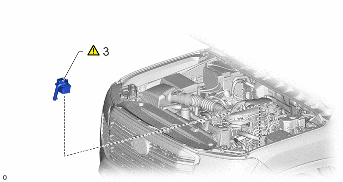
1.313,1.698 1.646,1.083 1.646,1.083 1.729,1.083 true 2.146,0.927 2.938,1.26 0.792,0.333 18 false 3
| Procedure | Part Name Code |
|
|
|
|
|---|---|---|---|---|---|
| 3 | AIR FILTER ASSEMBLY | 17810D | () |
- | - |
PROCEDURE

 17341X 1.INSTALL NO. 1 AIR HOSE
- HINT:
-
Perform this procedure only when replacement of the No. 1 air hose is necessary.
a.
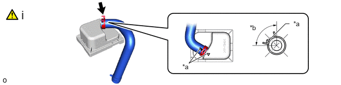
4.344,1.135 3.969,1.333 3.969,1.333 4.208,1.021 true 6.083,0.5 6,0.5 6,0.5 5.667,0.833 true 3.833,1.323 4.083,1.49 0.25,0.167 10 false *a 6.167,0.417 6.417,0.583 0.25,0.167 10 false *a 5.25,0.5 5.5,0.667 0.25,0.167 10 false *b 0.448,0.167 0.729,0.521 0.281,0.354 18 false i
| *a | Matchmark | *b | 90° |
i.
Install the No. 1 air hose to the upper filter element case and slide the hose clip to secure it.
- NOTICE:
-
Align the hose and the hose clip at the locations shown in the illustration and install them.
17813A 2.INSTALL PREFILTER
17810D 3.INSTALL AIR FILTER ASSEMBLY
a.
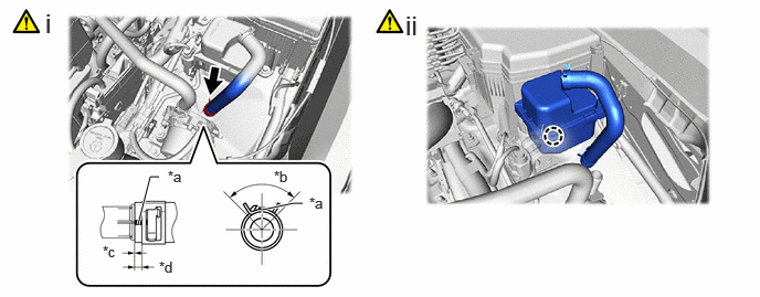
1.302,2.115 1.417,1.667 1.417,1.667 1.5,1.667 true 2.469,1.979 2.771,1.917 2.771,1.917 2.854,1.917 true 1.583,1.583 1.75,1.75 0.167,0.167 10 false *a 2.583,1.583 2.75,1.75 0.167,0.167 10 false *b 2.917,1.833 3.083,2 0.167,0.167 10 false *a 0.427,0.073 0.771,0.438 0.344,0.365 18 false i 3.823,0.094 4.167,0.458 0.344,0.365 18 false ii 0.969,2.292 1.135,2.458 0.167,0.167 10 false *c 1.5,2.438 1.667,2.604 0.167,0.167 10 false *d
| *a | Paint Mark | *b | 90° |
| *c | 2 mm (0.0787 in.) or less | *d | 2 to 7 mm (0.0788 to 0.2755 in.) |
i.
Connect the No. 1 air hose to the air pump assembly and slide the hose clip to secure it.
- NOTICE:
-
·
Align the hose and the hose clip at the locations shown in the illustration and install them.
·Make sure the No. 1 air hose is securely inserted to the stopper.
ii.
Attach the claw to install the air filter assembly.
- NOTICE:
-
Push in the air filter assembly until a click sound is heard.