RM38G0E _51 Engine / Hybrid System _101531 1GR-FE EMISSION CONTROL _0474408 AIR PUMP A
1GR-FE EMISSION CONTROL AIR PUMP INSTALLATION
CAUTION / NOTICE / HINT
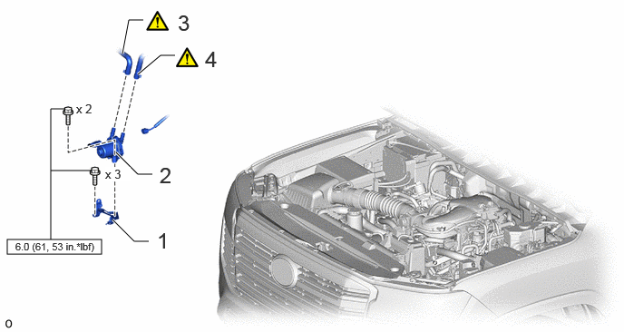
COMPONENTS (INSTALLATION)
0.083,2.75 1.167,2.917 1.083,0.167 1.583,0.854 1.844,0.635 1.844,0.635 2.01,0.635 true 1.333,1.75 1.583,2 1.583,2 1.75,2 true 1.292,2.521 1.542,2.771 1.542,2.771 1.708,2.771 true 0.75,1.25 0.583,1.25 0.583,1.25 0.583,2.75 false 0.583,1.958 1.052,1.958 false 1.406,0.615 1.479,0.229 1.479,0.229 1.646,0.229 true 2.354,0.531 2.948,0.854 0.594,0.323 18 false 4 2.042,0.115 2.615,0.5 0.573,0.385 18 false 3 1.802,2.615 2.052,2.948 0.25,0.333 18 false 1 1.833,1.865 2.083,2.198 0.25,0.333 18 false 2 1.208,1.917 1.5,2.083 0.292,0.167 10 true x 3 0.875,1.167 1.333,1.365 0.458,0.198 10 false x 2 0.177,2.76 2.625,2.917 2.448,0.156 8 false 6.0 (61, 53 in.*lbf)
| Procedure | Part Name Code |

|

|

|
|
|---|---|---|---|---|---|
| 1 | AIR PUMP BRACKET | 17314C | - | - | - |
| 2 | AIR PUMP ASSEMBLY | 17610C | - | - | - |
| 3 | NO. 2 AIR HOSE | 17342R | ( ) |
- | - |
| 4 | NO. 1 AIR HOSE | 17341X | () |
- | - |
PROCEDURE

 17314C 1.INSTALL AIR PUMP BRACKET
- Torque:
- 6.0 N*m (61 kgf*cm, 53 in.*lbf)
17610C 2.INSTALL AIR PUMP ASSEMBLY
- Torque:
- 6.0 N*m (61 kgf*cm, 53 in.*lbf)
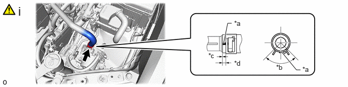
17342R 3.CONNECT NO. 2 AIR HOSE
a.
4.604,0.896 4.688,0.479 4.688,0.479 4.771,0.479 true 5.802,1.073 6.104,1.438 6.104,1.438 6.188,1.438 true 4.823,0.396 5.135,0.594 0.313,0.198 10 false *a 5.688,1.302 6,1.5 0.313,0.198 10 false *b 6.229,1.344 6.542,1.542 0.313,0.198 10 false *a 0.375,0.083 0.656,0.438 0.281,0.354 18 false i 4.292,1.063 4.604,1.26 0.313,0.198 10 false *c 4.823,1.219 5.135,1.417 0.313,0.198 10 false *d
| *a | Paint Mark | *b | 90° |
| *c | 2 mm (0.0787 in.) or less | *d | 2 to 7 mm (0.0788 to 0.2755 in.) |
i.
Connect the No. 2 air hose to the air pump assembly and slide the hose clip to secure it.
- NOTICE:
-
·
Align the hose and the hose clip at the locations shown in the illustration and install them.
·Make sure the No. 2 air hose is securely inserted to the stopper.
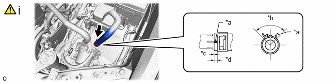
17341X 4.CONNECT NO. 1 AIR HOSE
a.
4.604,0.896 4.688,0.479 4.688,0.479 4.771,0.479 true 5.813,0.792 6.146,0.688 6.146,0.688 6.229,0.688 true 4.823,0.396 5.135,0.594 0.313,0.198 10 false *a 5.719,0.302 6.031,0.5 0.313,0.198 10 false *b 6.281,0.604 6.594,0.802 0.313,0.198 10 false *a 0.385,0.073 0.667,0.427 0.281,0.354 18 false i 4.292,1.063 4.604,1.26 0.313,0.198 10 false *c 4.823,1.198 5.135,1.396 0.313,0.198 10 false *d
| *a | Paint Mark | *b | 90° |
| *c | 2 mm (0.0787 in.) or less | *d | 2 to 7 mm (0.0788 to 0.2755 in.) |
i.
Connect the No. 1 air hose to the air pump assembly and slide the hose clip to secure it.
- NOTICE:
-
·
Align the hose and the hose clip at the locations shown in the illustration and install them.
·Make sure the No. 1 air hose is securely inserted to the stopper.