AXLE AND DIFFERENTIAL FRONT DIFFERENTIAL LOCK POSITION SWITCH INSTALLATION
CAUTION / NOTICE / HINT
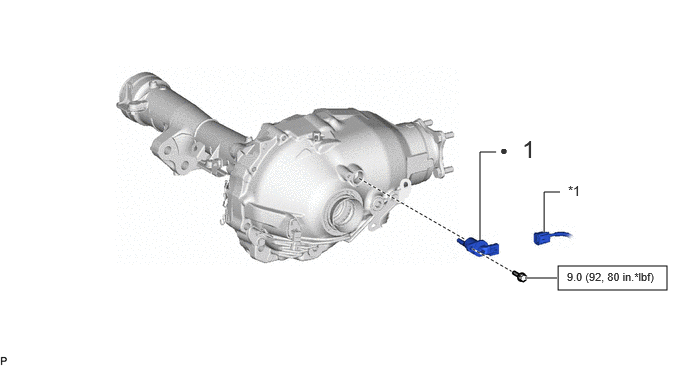
| Procedure | Part Name Code |

|

|

|
|
|---|---|---|---|---|---|
| 1 | NO. 1 4 WHEEL DRIVE POSITION SWITCH | 84546 | - | - | - |
| *1 | CONNECTOR | - | - |

|
N*m (kgf*cm, ft.*lbf): Specified torque | ● | Non-reusable part |
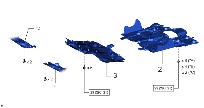
| Procedure | Part Name Code |
|
|
|
|
|---|---|---|---|---|---|
| 2 | NO. 2 ENGINE UNDER COVER ASSEMBLY | 51420 | - | - | - |
| 3 | NO. 1 ENGINE UNDER COVER ASSEMBLY | 51410 | - | - | - |
| *A | for V35A-FTS, w/ Cover | *B | for V35A-FTS, w/o Cover |
| *C | for 1GR-FE | - | - |
| *1 | ENGINE SIDE COVER SUB-ASSEMBLY LH | *2 | ENGINE SIDE COVER SUB-ASSEMBLY RH |
|
|
N*m (kgf*cm, ft.*lbf): Specified torque | - | - |
PROCEDURE

 84546 1.INSTALL NO. 1 4 WHEEL DRIVE POSITION SWITCH

Install a new No. 1 4 wheel drive position switch with the bolt.
- NOTICE:
-
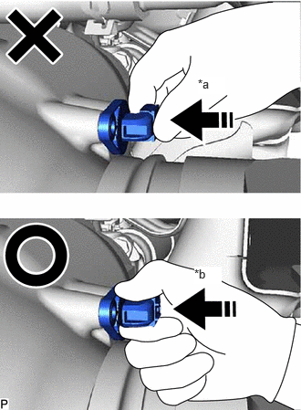 2.26,0.875 2.573,1.073 0.313,0.198 10 true *a 2.219,3.042 2.531,3.24 0.313,0.198 10 true *b
*a NG *b OK
-
When inserting the No. 1 4 wheel drive position switch into the differential carrier assembly, do not push it in by applying a weight to the upper surface of the connector as shown in the figure (* a). As shown in the figure (* b), support and assemble the connector neck.
- Torque:
- 9.0 N*m (92 kgf*cm, 80 in.*lbf)
51420 2.INSTALL NO. 2 ENGINE UNDER COVER ASSEMBLY
for V35A-FTS: Click hereEngine / Hybrid System>V35A-FTS (ENGINE MECHANICAL)>ENGINE ASSEMBLY>INSTALLATION
for 1GR-FE: Click hereEngine / Hybrid System>1GR-FE (ENGINE MECHANICAL)>ENGINE ASSEMBLY>INSTALLATION
51410 3.INSTALL NO. 1 ENGINE UNDER COVER ASSEMBLY
for V35A-FTS: Click hereEngine / Hybrid System>V35A-FTS (ENGINE MECHANICAL)>ENGINE ASSEMBLY>INSTALLATION
for 1GR-FE: Click hereEngine / Hybrid System>1GR-FE (ENGINE MECHANICAL)>ENGINE ASSEMBLY>INSTALLATION