1GR-FE ENGINE MECHANICAL ENGINE ASSEMBLY INSTALLATION
CAUTION / NOTICE / HINT
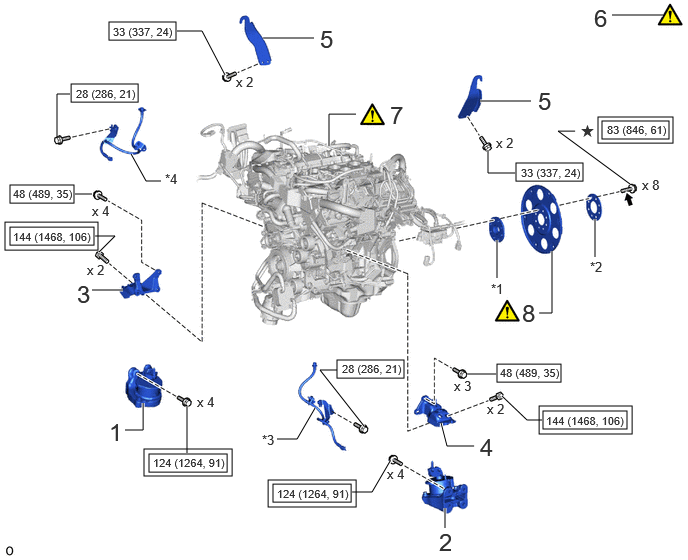
| Procedure | Part Name Code |

|

|

|
|
|---|---|---|---|---|---|
| 1 | FRONT ENGINE MOUNTING INSULATOR RH | 12361E | - | - | - |
| 2 | FRONT ENGINE MOUNTING INSULATOR LH | 12362A | - | - | - |
| 3 | FRONT NO. 1 ENGINE MOUNTING BRACKET RH | 12311 | - | - | - |
| 4 | FRONT NO. 1 ENGINE MOUNTING BRACKET LH | 12315 | - | - | - |
| 5 | INSTALL ENGINE HANGER | - | - | - | - |
| 6 | REMOVE ENGINE STAND | - | ( ) |
- | - |
| 7 | ENGINE ASSEMBLY | - | () |
- | - |
| 8 | DRIVE PLATE AND RING GEAR SUB-ASSEMBLY | 32101 | () |
- | - |
| *1 | FRONT DRIVE PLATE SPACER | *2 | REAR DRIVE PLATE SPACER |
| *3 | FRONT NO. 2 FLEXIBLE HOSE BRACKET LH | *4 | FRONT NO. 2 FLEXIBLE HOSE BRACKET RH |

|
Tightening torque for "Major areas involving basic vehicle performance such as moving/turning/stopping": N*m (kgf*cm, ft.*lbf) |

|
N*m (kgf*cm, ft.*lbf): Specified torque |
| ★ | Precoated part |

|
Adhesive 1324 |
| Procedure | Part Name Code |
|
|
|
|
|---|---|---|---|---|---|
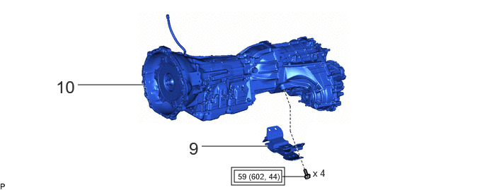
| 9 | REAR ENGINE MOUNTING INSULATOR | 12371A | - | - | |
| 10 | AUTOMATIC TRANSMISSION ASSEMBLY | 35000 | - | - | - |
|
|
Tightening torque for "Major areas involving basic vehicle performance such as moving/turning/stopping": N*m (kgf*cm, ft.*lbf) | - | - |
| Procedure | Part Name Code |
|
|
|
|
|---|---|---|---|---|---|
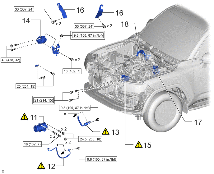
| 11 | COMPRESSOR ASSEMBLY WITH MAGNET CLUTCH | - | () |
- | - |
| 12 | NO. 1 COOLER REFRIGERANT DISCHARGE HOSE | 88711 | () |
- | - |
| 13 | SUCTION HOSE SUB-ASSEMBLY | 88704 | () |
- | - |
| 14 | GENERATOR ASSEMBLY | 27060 | - | - | - |
| 15 | VANE PUMP ASSEMBLY | 44310 | () |
- | - |
| 16 | ENGINE HANGER | - | - | - | - |
| 17 | NO. 1 AND NO. 2 FUEL PIPES | 23801P | - | - | - |
| 18 | WATER HOSE SUB-ASSEMBLY | - | - | - | - |
|
|
Tightening torque for "Major areas involving basic vehicle performance such as moving/turning/stopping": N*m (kgf*cm, ft.*lbf) |
|
N*m (kgf*cm, ft.*lbf): Specified torque |
| ● | Non-reusable part |
|
Compressor oil ND-OIL 8 or equivalent |
| Procedure | Part Name Code |
|
|
|
|
|---|---|---|---|---|---|
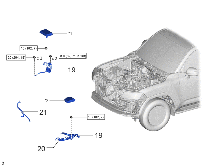
| 19 | ENGINE WIRE | 82121 | - | - | - |
| 20 | ECM CONNECTOR | - | - | - | - |
| 21 | OIL COOLER TUBE AND OIL COOLER HOSE | - | - | - | - |
| *1 | NO. 1 RELAY BLOCK COVER | *2 | NO. 2 RELAY BLOCK COVER |
|
|
N*m (kgf*cm, ft.*lbf): Specified torque | - | - |
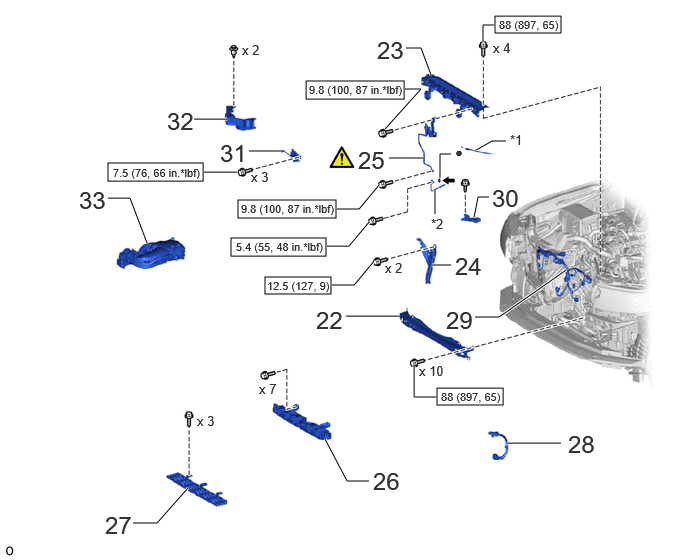
| Procedure | Part Name Code |
|
|
|
|
|---|---|---|---|---|---|
| 22 | FRONT CROSS MEMBER | 57161C | - | - | - |
| 23 | UPPER RADIATOR SUPPORT SUB-ASSEMBLY | 53205 | - | - | - |
| 24 | HOOD LOCK SUPPORT BRACE SUB-ASSEMBLY | 53209B | - | - | - |
| 25 | AIR CONDITIONING TUBE AND ACCESSORY ASSEMBLY AND NO. 2 AIR CONDITIONING TUBE AND ACCESSORY ASSEMBLY | 88710E | () |
- | - |
| 26 | FRONT BUMPER CENTER UPPER RETAINER | 52521 | - | - | - |
| 27 | FRONT BUMPER ENERGY ABSORBER (w/o Winch) | 52611 | - | - | - |
| 28 | EXTENSION WIRE ASSEMBLY (w/ Winch) | 82090A | - | - | - |
| 29 | ENGINE ROOM MAIN WIRE | 82111 | - | - | - |
| 30 | HOOD LOCK CONTROL CABLE COVER | 53629 | - | - | - |
| 31 | HOOD LOCK ASSEMBLY | 53510 | - | - | - |
| 32 | HOOD LOCK RELEASE LEVER PROTECTOR | 53525 | - | - | - |
| 33 | INTAKE AIR SURGE TANK | 17129 | - | - | - |
| *1 | HOOD LOCK CONTROL CABLE | *2 | COOLER REFRIGERANT LIQUID PIPE A |
|
|
N*m (kgf*cm, ft.*lbf): Specified torque | ● | Non-reusable part |
|
|
Compressor oil ND-OIL 8 or equivalent | - | - |
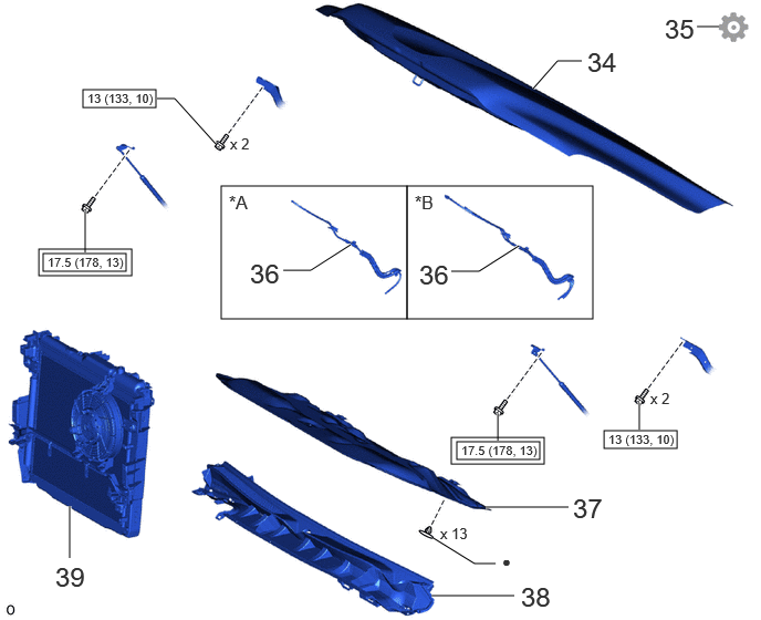
| Procedure | Part Name Code |
|
|
|
|
|---|---|---|---|---|---|
| 34 | HOOD SUB-ASSEMBLY | 53301 | - | - | - |
| 35 | ADJUST HOOD SUB-ASSEMBLY | 53301 | - | - | () |
| 36 | WINDSHIELD WASHER HOSE ASSEMBLY | 85370 | - | - | - |
| 37 | HOOD INSULATOR | 53341B | - | - | - |
| 38 | COWL TOP VENTILATOR LOUVER SUB-ASSEMBLY | 55708 | - | - | - |
| 39 | RADIATOR ASSEMBLY | 16400 | - | - | - |
| *A | w/ Heater | *B | w/o Heater |
|
|
Tightening torque for "Major areas involving basic vehicle performance such as moving/turning/stopping": N*m (kgf*cm, ft.*lbf) |
|
N*m (kgf*cm, ft.*lbf): Specified torque |
| ● | Non-reusable part | - | - |
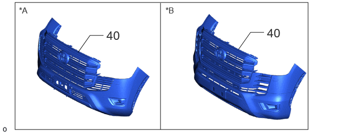
| Procedure | Part Name Code |
|
|
|
|
|---|---|---|---|---|---|
| 40 | FRONT BUMPER ASSEMBLY | - | - | - | - |
| *A | for Standard | *B | for Aero Type |
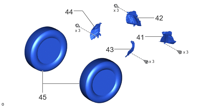
| Procedure | Part Name Code |
|
|
|
|
|---|---|---|---|---|---|
| 41 | FRONT FENDER APRON TRIM PACKING D | 53785B | - | - | - |
| 42 | FRONT FENDER APRON TRIM PACKING C | 53784 | - | - | - |
| 43 | FRONT FENDER APRON TRIM PACKING B | 53783 | - | - | - |
| 44 | FRONT FENDER APRON TRIM PACKING A | 53782 | - | - | - |
| 45 | FRONT WHEEL | - | - | - | - |
| Procedure | Part Name Code |
|
|
|
|
|---|---|---|---|---|---|
| 46 | CONNECT CABLE TO NEGATIVE BATTERY TERMINAL | - | - | - | - |
| 47 | INITIALIZATION AFTER RECONNECTING BATTERY TERMINAL | - | - | - | () |
| 48 | ADD ENGINE OIL | - | - | () |
- |
| 49 | ADD AUTOMATIC TRANSMISSION FLUID | - | - | () |
- |
| 50 | ADD COOLANT | - | - | () |
- |
| 51 | INSPECT SHIFT LEVER POSITION | - | () |
- | - |
| 52 | ADD AND ADJUST AUTOMATIC TRANSMISSION FLUID | - | - | () |
- |
| 53 | CHARGE AIR CONDITIONING SYSTEM WITH REFRIGERANT | - | () |
- | - |
| 54 | WARM UP ENGINE | - | () |
- | - |
| 55 | INSPECT FOR COOLANT LEAK | - | () |
- | - |
| 56 | INSPECT FOR OIL LEAK | - | () |
- | - |
| 57 | INSPECT FOR FUEL LEAK | - | () |
- | - |
| 58 | INSPECT FOR EXHAUST GAS LEAK | - | - | - | () |
| 59 | INSPECT FOR REFRIGERANT LEAK | - | () |
- | - |
| 60 | RESET MEMORY | - | - | - | () |
| 61 | ATF THERMAL DEGRADATION ESTIMATE RESET | - | - | - | () |
| 62 | INSPECT THROTTLE WITH THROTTLE POSITION SENSOR BODY ASSEMBLY | 22030 | () |
- | - |
| 63 | INSPECT IGNITION TIMING | - | () |
- | - |
| 64 | INSPECT ENGINE IDLE SPEED | - | () |
- | - |
| 65 | INSPECT CO/HC | - | () |
- | - |
| 66 | INSPECT ENGINE COOLANT LEVEL IN RESERVOIR | - | () |
- | - |
| 67 | INSPECT ENGINE OIL LEVEL | - | () |
- | - |
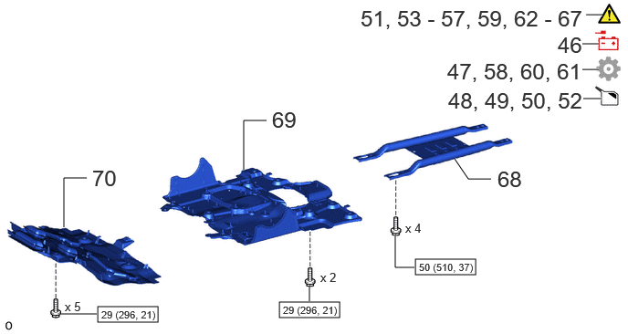
| 68 | OIL PAN PROTECTOR ASSEMBLY | 51440 | - | - | - |
| 69 | NO. 2 ENGINE UNDER COVER ASSEMBLY | 51420 | - | - | - |
| 70 | NO. 1 ENGINE UNDER COVER ASSEMBLY | 51410 | - | - | - |
|
|
N*m (kgf*cm, ft.*lbf): Specified torque | - | - |
PROCEDURE

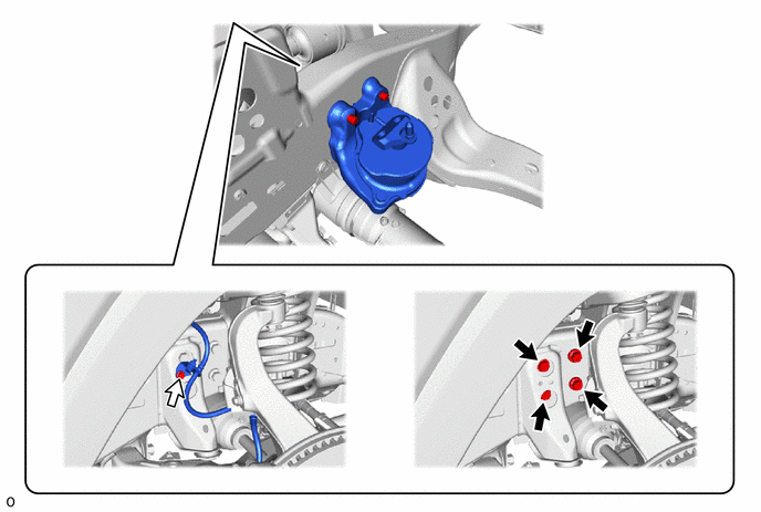
 12361E 1.INSTALL FRONT ENGINE MOUNTING INSULATOR RH
- HINT:
-
Perform this procedure only when replacement of the front engine mounting insulator RH is necessary.
|
|
Bolt A |

|
Bolt B |
- Torque:
- for bolt A : 124 N*m (1264 kgf*cm, 91 ft.*lbf)
- for bolt B : 28 N*m (286 kgf*cm, 21 ft.*lbf)
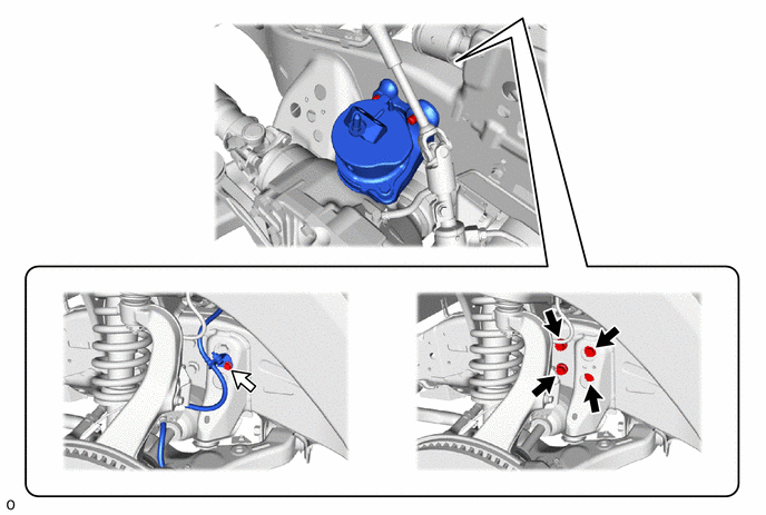
12362A 2.INSTALL FRONT ENGINE MOUNTING INSULATOR LH
- HINT:
-
Perform this procedure only when replacement of the front engine mounting insulator LH is necessary.
|
|
Bolt A |
|
Bolt B |
- Torque:
- for bolt A : 124 N*m (1264 kgf*cm, 91 ft.*lbf)
- for bolt B : 28 N*m (286 kgf*cm, 21 ft.*lbf)
12311 3.INSTALL FRONT NO. 1 ENGINE MOUNTING BRACKET RH
- Torque:
- 48 N*m (489 kgf*cm, 35 ft.*lbf)
12315 4.INSTALL FRONT NO. 1 ENGINE MOUNTING BRACKET LH
- Torque:
- 48 N*m (489 kgf*cm, 35 ft.*lbf)
5.INSTALL ENGINE HANGER
6.REMOVE ENGINE STAND
7.INSTALL ENGINE ASSEMBLY
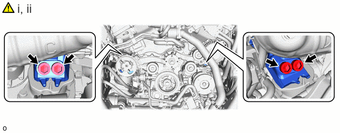
Slowly lower the engine into the engine compartment.
Using a 17 mm hexagon wrench, install the front engine mounting insulator LH and front engine mounting insulator RH with the 4 hexagon socket head cap bolts.
- Torque:
- 144 N*m (1468 kgf*cm, 106 ft.*lbf)
32101 8.INSTALL DRIVE PLATE AND RING GEAR SUB-ASSEMBLY
|
|
Click here() |
12371A 9.INSTALL REAR ENGINE MOUNTING INSULATOR
35000 10.INSTALL AUTOMATIC TRANSMISSION ASSEMBLY
11.INSTALL COMPRESSOR WITH MAGNET CLUTCH
|
|
Click here() |
88711 12.CONNECT NO. 1 COOLER REFRIGERANT DISCHARGE HOSE
|
|
Click here() |
88704 13.CONNECT SUCTION HOSE SUB-ASSEMBLY
|
|
Click here() |
27060 14.INSTALL GENERATOR ASSEMBLY
44310 15.CONNECT VANE PUMP ASSEMBLY
|
|
Click here() |
16.REMOVE ENGINE HANGER
23801P 17.CONNECT NO. 1 AND NO. 2 FUEL PIPES
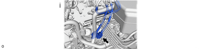
Connect the No. 1 and No. 2 fuel pipes.
Click hereEngine / Hybrid System>1GR-FE (FUEL)>FUEL SYSTEM>PRECAUTION
18.CONNECT WATER HOSE SUB-ASSEMBLY
82121 19.CONNECT ENGINE WIRE
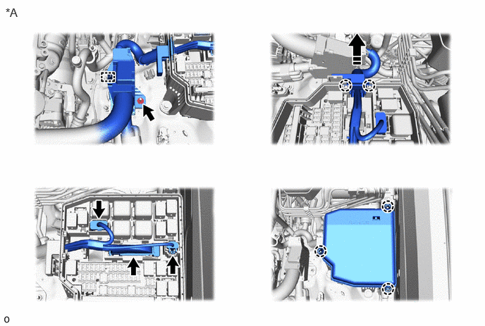
| *A | for LH Side | - | - |

|
Install in this Direction | - | - |
- Torque:
- 10 N*m (102 kgf*cm, 7 ft.*lbf)
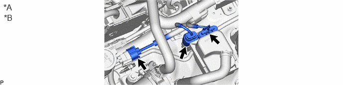
| *A | for LH Side | *B | w/ Secondary Air Injection System |
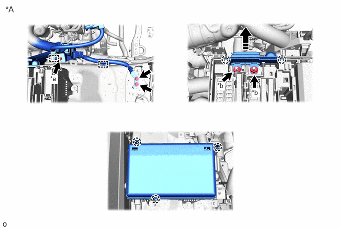
| *A | for RH Side | - | - |
| *a | Nut A | *b | Nut B |
|
|
Install in this Direction | - | - |
- Torque:
- for bolt : 20 N*m (204 kgf*cm, 15 ft.*lbf)
- for nut A : 10 N*m (102 kgf*cm, 7 ft.*lbf)
- for nut B : 8.0 N*m (82 kgf*cm, 71 in.*lbf)
20.CONNECT ECM CONNECTOR
21.INSTALL OIL COOLER TUBE AND OIL COOLER HOSE
57161C 22.INSTALL FRONT CROSS MEMBER
- Torque:
- 88 N*m (897 kgf*cm, 65 ft.*lbf)
53205 23.INSTALL UPPER RADIATOR SUPPORT SUB-ASSEMBLY
- Torque:
- 88 N*m (897 kgf*cm, 65 ft.*lbf)
53209B 24.INSTALL HOOD LOCK SUPPORT BRACE SUB-ASSEMBLY
- Torque:
- 12.5 N*m (127 kgf*cm, 9 ft.*lbf)
88710E 25.INSTALL AIR CONDITIONING TUBE AND ACCESSORY ASSEMBLY AND NO. 2 AIR CONDITIONING TUBE AND ACCESSORY ASSEMBLY
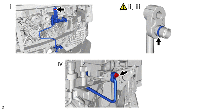
Install the air conditioning tube and accessory assembly and No. 2 air conditioning tube and accessory assembly with the bolt.
- Torque:
- 9.8 N*m (100 kgf*cm, 87 in.*lbf)
Remove the vinyl tape from the cooler refrigerant liquid pipe A and connecting part of the air conditioning tube and accessory assembly and No. 2 air conditioning tube and accessory assembly and then sufficiently apply compressor oil to a new O-ring and the fitting surface of the cooler refrigerant liquid pipe A.
- Compressor Oil:
-
ND-OIL 8 or equivalent
Install the O-ring to the cooler refrigerant liquid pipe A.
- NOTICE:
-
Keep the O-ring and O-ring fitting surface free of foreign matter.
Install the cooler refrigerant liquid pipe A to the air conditioning tube and accessory assembly and No. 2 air conditioning tube and accessory assembly with the bolt.
- Torque:
- 5.4 N*m (55 kgf*cm, 48 in.*lbf)
52521 26.INSTALL FRONT BUMPER CENTER UPPER RETAINER
52611 27.INSTALL FRONT BUMPER ENERGY ABSORBER (w/o Winch)
82090A 28.INSTALL EXTENSION WIRE ASSEMBLY (w/ Winch)
82111 29.CONNECT ENGINE ROOM MAIN WIRE
53629 30.INSTALL HOOD LOCK CONTROL CABLE COVER
53510 31.INSTALL HOOD LOCK ASSEMBLY
53525 32.INSTALL HOOD LOCK RELEASE LEVER PROTECTOR
17129 33.INSTALL INTAKE AIR SURGE TANK
53301 34.INSTALL HOOD SUB-ASSEMBLY
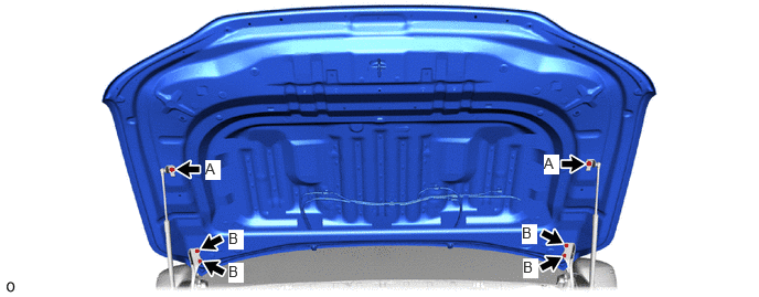
- Torque:
- for bolt A : 17.5 N*m (178 kgf*cm, 13 ft.*lbf)
- for bolt B : 13 N*m (133 kgf*cm, 10 ft.*lbf)
53301 35.ADJUST HOOD SUB-ASSEMBLY
85370 36.INSTALL WINDSHIELD WASHER HOSE ASSEMBLY
53341B 37.INSTALL HOOD INSULATOR
55708 38.INSTALL COWL TOP VENTILATOR LOUVER SUB-ASSEMBLY
16400 39.INSTALL RADIATOR ASSEMBLY
40.INSTALL FRONT BUMPER ASSEMBLY
for Standard:
Click hereVehicle Exterior>EXTERIOR PANELS / TRIM>FRONT BUMPER (for Standard)>INSTALLATION
for Aero Type:
Click hereVehicle Exterior>EXTERIOR PANELS / TRIM>FRONT BUMPER (for Aero Type)>INSTALLATION
53785B 41.INSTALL FRONT FENDER APRON TRIM PACKING D
53784 42.INSTALL FRONT FENDER APRON TRIM PACKING C
53783 43.INSTALL FRONT FENDER APRON TRIM PACKING B
53782 44.INSTALL FRONT FENDER APRON TRIM PACKING A
45.INSTALL FRONT WHEEL
46.CONNECT CABLE TO NEGATIVE BATTERY TERMINAL
47. INITIALIZATION AFTER RECONNECTING BATTERY TERMINAL
Click hereGeneral>SETUP>WHEN DISCONNECTING OR RECONNECTING BATTERY TERMINAL>WORK PROCEDURE
- HINT:
-
When disconnecting and reconnecting the battery, there is an automatic learning function that completes learning when the respective system is used.
-
Click hereGeneral>SETUP>WHEN DISCONNECTING OR RECONNECTING BATTERY TERMINAL>AUTOMATIC LEARNING CHART
48.ADD ENGINE OIL
49.ADD AUTOMATIC TRANSMISSION FLUID
50.ADD COOLANT
51.INSPECT SHIFT LEVER POSITION
52.ADD AND ADJUST AUTOMATIC TRANSMISSION FLUID
53.CHARGE AIR CONDITIONING SYSTEM WITH REFRIGERANT
54. WARM UP ENGINE
55.INSPECT FOR COOLANT LEAK
56.INSPECT FOR OIL LEAK
57.INSPECT FOR FUEL LEAK
58.INSPECT FOR EXHAUST GAS LEAK
59.INSPECT FOR REFRIGERANT LEAK
60.RESET MEMORY
|
|
Click here() |
61. ATF THERMAL DEGRADATION ESTIMATE RESET
|
|
Click here() |
22030 62.INSPECT THROTTLE WITH THROTTLE POSITION SENSOR BODY ASSEMBLY
63.INSPECT IGNITION TIMING
64.INSPECT ENGINE IDLE SPEED
65.INSPECT CO/HC
66.INSPECT ENGINE COOLANT LEVEL IN RESERVOIR
67.INSPECT ENGINE OIL LEVEL
51440 68.INSTALL OIL PAN PROTECTOR ASSEMBLY
51420 69.INSTALL NO. 2 ENGINE UNDER COVER ASSEMBLY
- Torque:
- 29 N*m (296 kgf*cm, 21 ft.*lbf)
51410 70.INSTALL NO. 1 ENGINE UNDER COVER ASSEMBLY
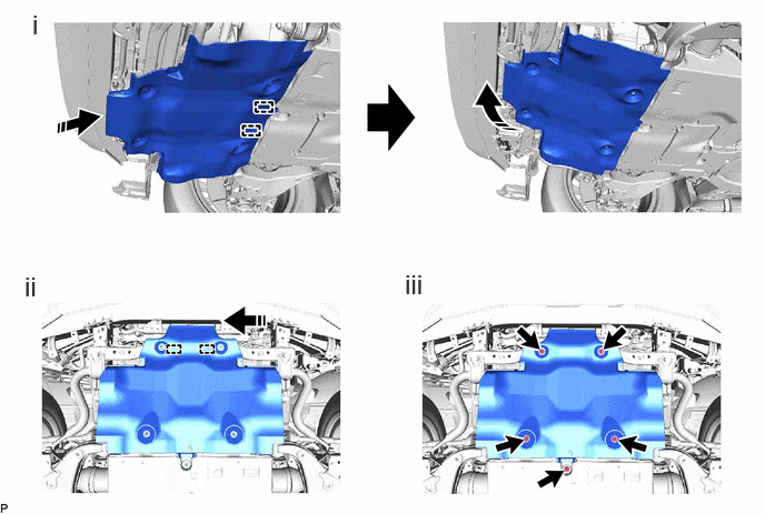
|
|
Install in this Direction | - | - |
Set the No. 1 engine under cover assembly to the vehicle side while attaching the 2 temporary holding guides of the No. 1 engine under cover assembly to the vehicle frame as shown in the illustration.
Move the side of the No. 1 engine under cover assembly facing the front of the vehicle and attach the 2 temporary holding guides to the vehicle frame.
Install the 5 bolts.
- Torque:
- 29 N*m (296 kgf*cm, 21 ft.*lbf)