F33A-FTV BATTERY / CHARGING CHARGING SYSTEM ON-VEHICLE INSPECTION
CAUTION / NOTICE / HINT
The necessary procedures (adjustment, calibration, initialization, or registration) that must be performed after parts are removed and installed, or replaced when inspecting battery are shown below.
| Replaced Part or Performed Procedure | Necessary Procedure | Effect/Inoperative Function when Necessary Procedure not Performed | Link |
|---|---|---|---|
| Disconnect cable from negative battery terminal | Memorize steering angle neutral point | Parking assist monitor system | ( ) |
| Multi-terrain monitor system | () |
||
| Panoramic view monitor system | () |
- HINT:
-
When the cable is disconnected/reconnected to the battery terminal, systems temporarily stop operating. However, each system has a function that completes learning the first time the system is used.
-
·
Learning completes when vehicle is driven
Effect/Inoperative Function When Necessary Procedures are not Performed Necessary Procedures Link Stop and start system Drive the vehicle until stop and start control is permitted (approximately 5 to 60 minutes) ( )Lighting system (EXT) Cornering lights Drive the vehicle straight ahead at 35 km/h (22 mph) or more for 5 seconds or more. ( )Pre-collision system Lane tracing assist system Lane departure alert system Adaptive high beam system
·Learning completes when vehicle is operated normally
Effect/Inoperative Function When Necessary Procedures are not Performed Necessary Procedures Link Power back door system Fully close the back door by hand.
- HINT:
-
Initialization is not necessary if the above procedures are performed while the back door is closed.
( )Air conditioning system After the ignition switch is turned to ON, the servo motor and expansion valve standard position is recognized. -
PROCEDURE

 1. PRECAUTION
- NOTICE:
-
After the ignition switch is turned off, there may be a waiting time before disconnecting the negative (-) battery terminal.
-
Click hereGeneral>SETUP>WHEN DISCONNECTING OR RECONNECTING BATTERY TERMINAL>BEFORE DISCONNECTING BATTERY
2.CHECK BATTERY CONDITION
- NOTICE:
-
If the battery is weak or if the engine is difficult to start, recharge the battery and perform inspections again before returning the vehicle to the customer.
for LHD:
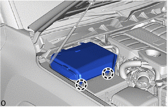
Detach the 2 claws and open the engine side cover RH.
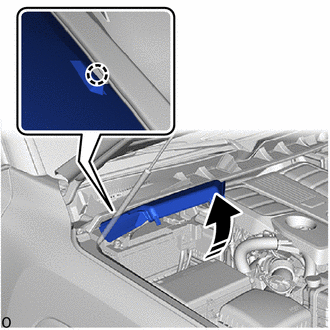

|
Lift in this Direction |
Fit the claw of the cowl top ventilator louver RH into the groove of the engine side cover RH and fix the engine side cover RH.
for RHD:
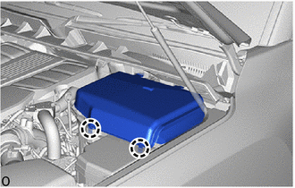
Detach the 2 claws and open the engine side cover LH.
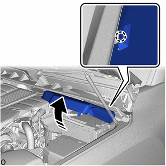
|
|
Lift in this Direction |
Fit the claw of the cowl top ventilator louver LH into the groove of the engine side cover LH and fix the engine side cover LH.
Check the battery for damage or deformation. If severe damage, deformation or leakage is found, replace the battery.
Check the electrolyte level in each cell.
If the electrolyte level is below the lower line, replace the battery.
If the electrolyte level is below the lower line, add distilled water to each cell. Then, recharge the battery and check the electrolyte specific gravity.
- Standard Specific Gravity:
-
1.25 or more at 20°C (68°F)
Check the voltage.
Turn the ignition switch off and turn on the headlights for 20 to 30 seconds. This will remove the surface charge from the battery.
Measure the battery voltage according to the value(s) in the table below.
- Standard Voltage:
-
Tester Connection Condition Specified Condition Positive (+) terminal - Negative (-) terminal 20°C (68°F) 12.3 V or higher
If the result is not as specified, recharge or replace the battery.
3.INSPECT BATTERY TERMINAL, BATTERY STATE SENSOR ASSEMBLY AND FUSIBLE LINK AND FUSE
for LHD:
Detach the 2 claws and open the engine side cover RH.
|
|
Lift in this Direction |
Fit the claw of the cowl top ventilator louver RH into the groove of the engine side cover RH and fix the engine side cover RH.
for RHD:
Detach the 2 claws and open the engine side cover LH.
|
|
Lift in this Direction |
Fit the claw of the cowl top ventilator louver LH into the groove of the engine side cover LH and fix the engine side cover LH.
Check whether the battery terminals and engine wire harness are loose or corroded.
Check whether the battery state sensor assembly is deformed or cracked.
- Torque:
- Positive (+) Battery Terminal : 5.0 N*m (51 kgf*cm, 44 in.*lbf)
- Negative (-) Battery Terminal (Battery State Sensor Assembly) : 5.4 N*m (55 kgf*cm, 48 in.*lbf)
- Wire Harness : 7.5 N*m (76 kgf*cm, 66 in.*lbf)
Check that the battery terminals are not loose or corroded.
If a terminal is loose or corroded, tighten or clean the terminal.
- Torque:
- Positive (+) Battery Terminal : 5.0 N*m (51 kgf*cm, 44 in.*lbf)
- Negative (-) Battery Terminal : 5.0 N*m (51 kgf*cm, 44 in.*lbf)
Measure the resistance of each fuse for the charging system.
- Standard Resistance:
-
Below 1 Ω
If the result is not as specified, replace the fuse.
16361A 4.INSPECT FAN AND GENERATOR V BELT
5.INSPECT GENERATOR WIRING
Visually check the generator wiring.
Check that the wiring is in good condition.
6.CHECK FOR ABNORMAL NOISE
Check for abnormal noises from the generator assembly.
Check that no abnormal noises are heard from the generator assembly while the engine is running.
7.INSPECT CHARGING CIRCUIT WITHOUT LOAD
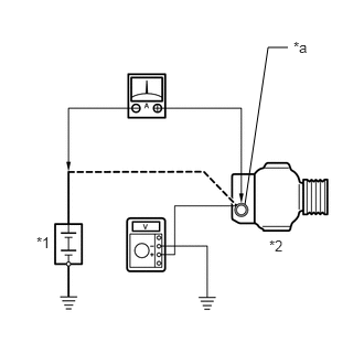
| *1 | Battery |
| *2 | Generator Assembly |
| *a | Terminal B |
Connect a voltmeter and an ammeter to the charging circuit as follows.
- HINT:
-
If a battery/generator assembly tester is available, connect the tester to the charging circuit in accordance with the manufacturer's instructions.
Disconnect the wire from terminal B of the generator assembly and connect it to the negative (-) lead of the ammeter.
Connect the ammeter positive (+) lead to terminal B of the generator assembly.
Connect the voltmeter positive (+) lead to terminal B of the generator assembly.
Ground the voltmeter negative (-) lead.
Check the charging circuit.
Maintain the engine speed at 2000 rpm and check the readings on the ammeter and voltmeter.
- Standard Current:
-
Specified Condition 10 A or higher
- Standard Voltage (w/ Stop and Start System):
-
Specified Condition 12.7 to 15.3 V
- Standard Voltage (w/o Stop and Start System):
-
Specified Condition 13.5 to 14.35 V
If the result is not as specified, repair or replace the generator assembly.
8.INSPECT CHARGING CIRCUIT WITH LOAD
With the engine running at 2000 rpm, turn the high beam headlights on and turn the heater blower switch to the "HI" position.
Check the reading on the ammeter.
- Standard Current:
-
Specified Condition 30 A or higher
If the result is not as specified, repair or replace the generator assembly.
- HINT:
-
If the battery is fully charged, the reading will sometimes be less than the standard current. In this case, add more electrical load (operate the wipers, rear window defogger, etc.) and check the reading on the ammeter again.
9.INSPECT CHARGING SYSTEM
Check the harness and connector.
Disconnect the B70 ECM connector.
Disconnect the C53 generator assembly connector.
w/ Stop and Start System:
Disconnect the B39 battery state sensor assembly connector.
Measure the resistance according to the value(s) in the table below.
- Standard Resistance:
-
Tester Connection Condition Specified Condition Click Location & Routing(B70,C53,B39)Location & Routingewd_type=routing;type=c,c,c;code=B70,C53,B39
B70-13 (LIN) - C53-2 (LIN) Always Below 1 Ω B70-13 (LIN) or C53-2 (LIN) - Body ground Ignition switch off
(while LIN communication is stopped)10 kΩ or higher B70-13 (LIN) - B39-2 (LIN)* Always Below 1 Ω B70-13 (LIN) or B39-2 (LIN) - Body ground* Ignition switch off
(while LIN communication is stopped)10 kΩ or higher
*: w/ Stop and Start System
If the result is not as specified, repair or replace the harness or connector.