Home › Power Source / Network › F33A-FTV (BATTERY / CHARGING) › GENERATOR (for DENSO Made) › from 2021.07
RM38G0E _57 Power Source / Network _106328 F33A-FTV BATTERY / CHARGING _0489034 GENERATOR(for DENSO Made) A

F33A-FTV BATTERY / CHARGING  GENERATOR(for DENSO Made)  REASSEMBLY  


CAUTION / NOTICE / HINT
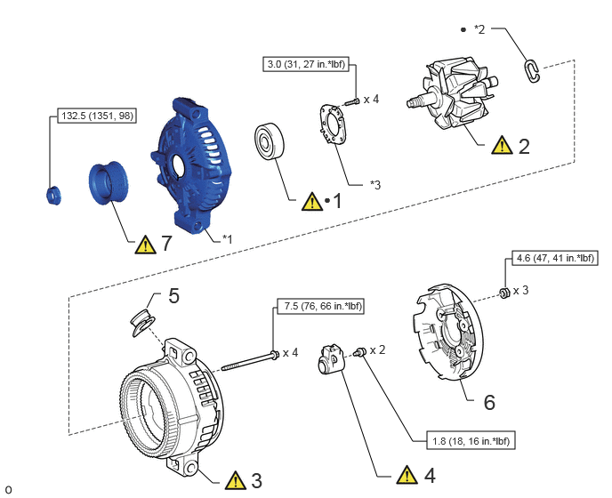
COMPONENTS (REASSEMBLY)
A484889N01
0.677,1.271 1.594,1.438 0.917,0.167 3.083,0.667 4.083,0.833 1,0.167 3.25,3.5 4.26,3.677 1.01,0.177 5,5.052 6.031,5.26 1.031,0.208 6,2.938 7,3.104 1,0.167 1.302,2.344 1.5,2.833 1.5,2.833 1.583,2.833 false 3.219,1.844 3.385,2.344 3.385,2.344 3.469,2.344 false 3.917,1.667 4.083,2.167 4.083,2.167 4.25,2.167 false 0.583,2.198 0.583,1.365 0.583,1.365 0.667,1.365 false 4.167,1.146 4.167,0.76 4.167,0.76 4.083,0.76 false 5.427,1.448 5.594,1.698 5.594,1.698 5.677,1.698 false 6.167,0.708 5.917,0.333 5.917,0.333 5.75,0.333 false 2.323,5.5 2.49,5.656 2.49,5.656 2.573,5.656 false 4,4.344 4.417,5.583 4.417,5.583 4.583,5.583 false 1.719,3.604 1.802,3.438 1.802,3.438 1.885,3.438 false 5.385,4.438 5.469,4.688 5.469,4.688 5.552,4.688 false 3.25,3.604 3.198,3.604 3.198,3.604 3.198,4.104 false 4.25,4.167 4.833,5.167 4.833,5.167 5,5.167 false 5.917,3.365 5.917,3.031 5.917,3.031 6,3.031 false 2.396,2.677 2.5,2.833 2.5,2.833 2.583,2.833 false 1.885,2.698 2.167,3.052 0.281,0.354 18 false 7 3.792,2.25 3.948,2.448 0.156,0.198 10 false ● 3.885,2.198 4.167,2.552 0.281,0.354 18 false 1 4.333,2.083 4.615,2.438 0.281,0.354 10 false *3 0.719,1.281 1.667,1.49 0.948,0.208 8 false 132.5 (1351, 98) 3.135,0.677 4.115,0.844 0.979,0.167 8 false 3.0 (31, 27 in.*lbf) 6.073,1.563 6.354,1.917 0.281,0.354 18 false 2 5.552,0.26 5.833,0.615 0.281,0.354 10 false *2 2.938,5.479 3.25,5.76 0.313,0.281 18 false 3 4.969,5.417 5.25,5.771 0.281,0.354 18 false 4 1.969,3.313 2.25,3.667 0.281,0.354 18 false 5 5.667,4.563 5.948,4.917 0.281,0.354 18 false 6 3.333,3.51 4.313,3.688 0.979,0.177 8 false 7.5 (76, 66 in.*lbf) 5.063,5.094 6.042,5.219 0.979,0.125 8 false 1.8 (18, 16 in.*lbf) 6.052,2.948 7.052,3.115 1,0.167 8 false 4.6 (47, 41 in.*lbf) 2.604,2.719 2.917,2.917 0.313,0.198 10 false *1 5.385,0.25 5.542,0.448 0.156,0.198 10 false ● 6.01,3.313 6.469,3.51 0.458,0.198 10 false x 3 4.333,4.01 4.792,4.208 0.458,0.198 10 false x 2 3.313,4.042 3.771,4.24 0.458,0.198 10 false x 4 4.26,1.073 4.719,1.271 0.458,0.198 10 false x 4

Procedure Part Name Code
Z101186

Z101188

Z101187

1 GENERATOR DRIVE END FRAME BEARING 27310B (Click here) - -
2 GENERATOR ROTOR ASSEMBLY 27330 (Click here) - -
3 GENERATOR COIL ASSEMBLY 27360 (Click here) - -
4 GENERATOR BRUSH HOLDER ASSEMBLY 27370 (Click here) - -
5 GENERATOR TERMINAL INSULATOR 27387B - - -
6 GENERATOR REAR END COVER 27039 - - -
7 GENERATOR PULLEY 27411 (Click here) - -

*1 GENERATOR DRIVE END FRAME *2 GENERATOR WASHER
*3 RETAINER PLATE - -
V100146

N*m (kgf*cm, ft.*lbf): Specified torque ● Non-reusable part

PROCEDURE

Hide 27310B 1.INSTALL GENERATOR DRIVE END FRAME BEARING
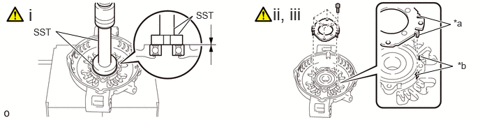
a.
A484883C01
1.375,0.969 0.833,0.469 0.833,0.469 1.458,0.604 true 2.604,0.427 2.875,0.24 2.875,0.24 2.667,0.51 true 6.271,0.24 6.729,0.365 6.729,0.365 6.26,0.521 true 6.229,1.115 6.76,0.99 6.76,0.99 6.281,0.844 true 2.927,0.146 3.385,0.344 0.458,0.198 10 false SST 0.5,0.396 0.958,0.594 0.458,0.198 10 false SST 6.771,0.26 6.958,0.458 0.188,0.198 10 false *a 6.833,0.896 7.094,1.167 0.26,0.271 10 false *b 0.427,0.073 0.906,0.406 0.479,0.333 18 false i 4.073,0.063 4.688,0.396 0.615,0.333 18 false ii, iii
*a Tab *b Cutout


i.

Using SST and a press, install a new generator drive end frame bearing.

SST
09950-60011  (09951-00470)
09950-70010  (09951-07100)


ii.

Fit the tabs of the retainer plate into the cutouts of the generator drive end frame to install the retainer plate.


iii.

Install the 4 screws.

Torque:
3.0 N*m (31 kgf*cm, 27 in.*lbf)


Hide 27330 2.INSTALL GENERATOR ROTOR ASSEMBLY
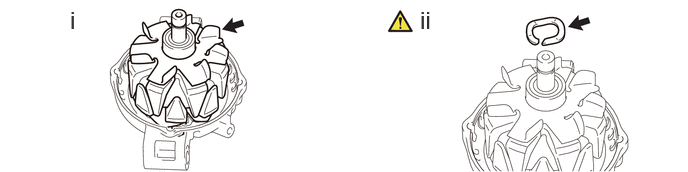
a.
A484888N01
0.729,0.063 1.01,0.417 0.281,0.354 18 false i 4.375,0.063 4.927,0.417 0.552,0.354 18 false ii

i.

Install the generator rotor assembly to the generator drive end frame.


ii.

Place a new generator washer on the generator rotor assembly.

NOTICE:

Make sure to install the washer so that its cutout faces the bearing side, as the washer must be installed in a specific direction.


Hide 27360 3.INSTALL GENERATOR COIL ASSEMBLY
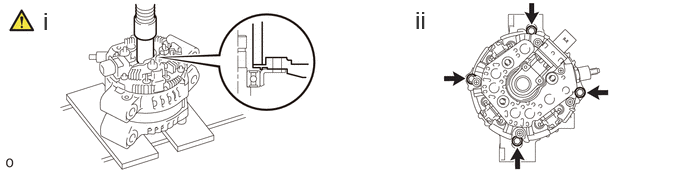
a.
A484884N01
0.448,0.073 0.729,0.427 0.281,0.354 18 false i 4.323,0.063 4.875,0.417 0.552,0.354 18 false ii

i.

Using a 21 mm deep socket wrench and press, slowly press in the generator coil assembly.


ii.

Install the 4 bolts.

Torque:
7.5 N*m (76 kgf*cm, 66 in.*lbf)


Hide 27370 4.INSTALL GENERATOR BRUSH HOLDER ASSEMBLY
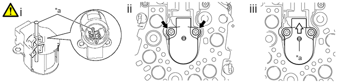
a.
A461910C01
0.813,0.479 1.219,0.302 1.219,0.302 1.948,0.615 true 6.365,1.094 6.365,0.865 false 1.208,0.854 1.49,1.208 0.281,0.354 18 false i 0.417,0.104 0.698,0.458 0.281,0.354 18 false i 2.698,0.031 2.979,0.385 0.281,0.354 18 false ii 5.302,0.031 5.583,0.385 0.281,0.354 18 false iii 1.167,0.135 1.479,0.333 0.313,0.198 10 false *a 6.292,1.146 6.604,1.344 0.313,0.198 10 false *a
*a Pin (1.0 mm) - -
V100136

Pull out - -


i.

While pushing the 2 brushes into the generator brush holder assembly, insert a 1.0 mm (0.0394 in.) pin into the generator brush holder assembly hole.


ii.

Install the generator brush holder assembly to the generator coil assembly with the 2 screws.

Torque:
1.8 N*m (18 kgf*cm, 16 in.*lbf)


iii.

Pull out the pin from the generator brush holder assembly hole.


Hide 27387B 5.INSTALL GENERATOR TERMINAL INSULATOR

Hide 27039 6.INSTALL GENERATOR REAR END COVER

Torque:
4.6 N*m (47 kgf*cm, 41 in.*lbf)

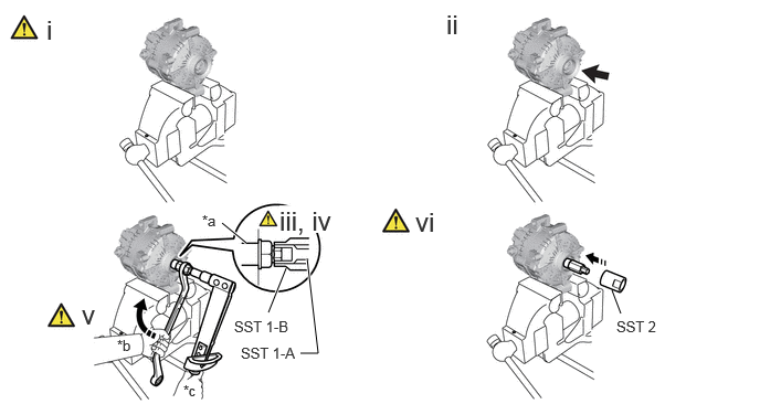
Hide 27411 7.INSTALL GENERATOR PULLEY

a.
A484886C01
5.771,2.74 5.854,2.958 false 2.094,2.104 2.323,2.292 true 2.531,2.948 2.698,2.531 true 2.896,2.438 3,3.333 3,3.333 2.833,3.333 true 0.438,0.135 0.719,0.49 0.281,0.354 18 false i 4.208,0.083 4.76,0.438 0.552,0.354 18 false ii 2.635,1.938 3.167,2.198 0.531,0.26 18 true iii, iv 0.771,2.823 1.052,3.177 0.281,0.354 18 false v 3.917,1.948 4.469,2.302 0.552,0.354 18 false vi 5.813,3 6.583,3.198 0.771,0.198 10 false SST 2 1.104,3.177 1.417,3.375 0.313,0.198 10 false *b 1.729,3.604 2.042,3.802 0.313,0.198 10 false *c 1.906,2 2.219,2.198 0.313,0.198 10 false *a 2.208,3 3.281,3.198 1.073,0.198 10 false SST 1-B 2.271,3.25 3.344,3.448 1.073,0.198 10 false SST 1-A
*a Rotor Shaft *b Hold
*c Turn - -


i.

Secure the generator drive end frame in a vise between aluminum plates.


ii.

Temporarily install the generator pulley by hand.


iii.

Install SST 1-A to the generator pulley shaft.

SST
09820-63011  (09820-06010, 09820-06021)


iv.

Install SST 1-B to SST 1-A.


v.

Hold SST 1-A with a torque wrench and turn SST 1-B clockwise with the specified torque.

Torque:
39 N*m (398 kgf*cm, 29 ft.*lbf)

NOTICE:

Make sure that SST is secured to the generator rotor shaft.


vi.

Insert SST 2 and attach it to the generator pulley nut.
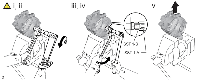


b.
A484887C01
4.813,1.042 4.667,1.427 true 4.979,0.969 5.083,1.844 5.083,1.844 4.917,1.844 true 0.458,0.052 1.031,0.406 0.573,0.354 18 false i, ii 2.479,0.052 3.177,0.385 0.698,0.333 18 false iii, iv 5.281,0.042 5.563,0.396 0.281,0.354 18 false v 0.521,2 0.833,2.198 0.313,0.198 10 false *a 1.323,2.552 1.635,2.75 0.313,0.198 10 false *b 3.177,2.323 3.49,2.521 0.313,0.198 10 false *b 4.219,2.417 4.531,2.615 0.313,0.198 10 false *a 4.333,1.76 5.406,1.958 1.073,0.198 10 false SST 1-A 4.292,1.458 5.365,1.656 1.073,0.198 10 false SST 1-B
*a Hold *b Turn


i.

Tighten the generator pulley nut by turning SST 1- A in the direction shown in the illustration.

Torque:
132.5 N*m (1351 kgf*cm, 98 ft.*lbf)


ii.

Remove SST 2 from the generator assembly.


iii.

Turn SST 1-B in the direction shown in the illustration and remove SST 1-A and B.


iv.

Turn the generator pulley and check that the generator pulley moves smoothly.


v.

Remove the generator drive end frame from the vise.