Home › Audio / Visual / Telematics › AUDIO / VIDEO › AUDIO AND VISUAL SYSTEM (for Radio and Display Type, except 12.3 Inch Display) › from 2021.07
RM38G0E _56 Audio / Visual / Telematics _100606 AUDIO / VIDEO _0467497 AUDIO AND VISUAL SYSTEM(for Radio and Display Type, except 12.3 Inch Display) C

AUDIO / VIDEO  AUDIO AND VISUAL SYSTEM(for Radio and Display Type, except 12.3 Inch Display)  B1579  Voice Recognition Microphone Disconnected  


DESCRIPTION

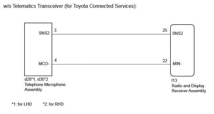
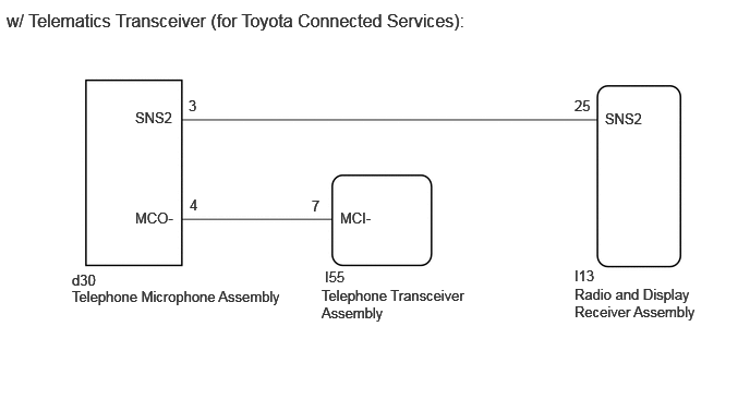
The radio and display receiver assembly and telephone microphone assembly are connected to each other using the microphone connection detection signal lines.

This DTC is stored when a microphone connection detection signal line is disconnected.

DTC No. Detection Item DTC Detection Condition Trouble Area DTC Output from Priority
B1579 Voice Recognition Microphone Disconnected Microphone signal is lost
·

Telephone microphone assembly

·

Radio and display receiver assembly

·

Harness or connector


Navigation System A

WIRING DIAGRAM

E379999E54
1.302,1.021 1.76,1.25 0.458,0.229 10 false SNS2 1.813,0.927 2.031,1.115 0.219,0.188 10 false 3 5.448,0.927 5.667,1.115 0.219,0.188 10 false 25 5.771,1.031 6.229,1.188 0.458,0.156 10 false SNS2 1.292,2.042 1.75,2.271 0.458,0.229 10 false MCO- 1.823,1.927 2.281,2.156 0.458,0.229 10 false 4 5.448,1.948 5.729,2.188 0.281,0.24 10 false 22 5.781,2.042 6.167,2.25 0.385,0.208 10 false MIN- 5.74,2.604 6.198,2.833 0.458,0.229 10 false I13 5.75,2.781 6.948,3.177 1.198,0.396 10 false Radio and Display Receiver Assembly 0.823,2.563 1.906,2.76 1.083,0.198 10 false d28*1, d30*2 0.823,2.74 2.25,3.229 1.427,0.49 10 false Telephone Microphone Assembly 0.396,3.396 1.479,3.594 1.083,0.198 10 false *1: for LHD 1.438,3.396 2.521,3.594 1.083,0.198 10 false *2: for RHD 0.115,0.094 5.115,0.458 5,0.365 12 false w/o Telematics Transceiver (for Toyota Connected Services):

E367057E34
0.063,0.094 4.76,0.396 4.698,0.302 12 false w/ Telematics Transceiver (for Toyota Connected Services): 1.292,1.042 1.75,1.229 0.458,0.188 10 false SNS2 1.292,2 1.75,2.188 0.458,0.188 10 false MCO- 3.25,2 3.708,2.188 0.458,0.188 10 false MCI- 5.781,1.052 6.24,1.24 0.458,0.188 10 false SNS2 0.688,2.594 1.146,2.781 0.458,0.188 10 false d30 0.688,2.75 2.792,2.948 2.104,0.198 10 false Telephone Microphone Assembly 3.104,2.563 3.563,2.75 0.458,0.188 10 false I55 3.073,2.74 4.469,3.198 1.396,0.458 10 false Telephone Transceiver Assembly 5.49,2.552 5.948,2.74 0.458,0.188 10 false I13 5.49,2.729 7.052,3.281 1.563,0.552 10 false Radio and Display Receiver Assembly 1.802,0.927 1.938,1.125 0.135,0.198 10 false 3 1.813,1.875 1.948,2.073 0.135,0.198 10 false 4 2.979,1.885 3.188,2.083 0.208,0.198 10 false 7 5.49,0.927 5.698,1.125 0.208,0.198 10 false 25


CAUTION / NOTICE / HINT

NOTICE:

When replacing the telematics transceiver, make sure to replace it with a new one. (w/ Telematics Transceiver)


HINT:

Depending on the parts that are replaced during vehicle inspection or maintenance, performing initialization, registration or calibration may be needed. Refer to Precaution for Audio and Visual System.

Click hereAudio / Visual / Telematics>AUDIO / VIDEO>AUDIO AND VISUAL SYSTEM (for Radio and Display Type, except 12.3 Inch Display)>PRECAUTION


PROCEDURE

1.CHECK VEHICLE TYPE
a.

Check the vehicle type.


Result:
Result Proceed to
w/o Telematics Transceiver (for Toyota Connected Services) A
w/ Telematics Transceiver (for Toyota Connected Services) B


A

2.CHECK HARNESS AND CONNECTOR (RADIO AND DISPLAY RECEIVER ASSEMBLY - TELEPHONE MICROPHONE ASSEMBLY)

B

4.CHECK HARNESS AND CONNECTOR (RADIO RECEIVER ASSEMBLY - TELEPHONE MICROPHONE ASSEMBLY AND TELEPHONE TRANSCEIVER ASSEMBLY)
2.CHECK HARNESS AND CONNECTOR (RADIO AND DISPLAY RECEIVER ASSEMBLY - TELEPHONE MICROPHONE ASSEMBLY)

Pre-procedure1

a.

Disconnect the I13 radio and display receiver assembly connector.


b.

Disconnect the d28*1 or d30*2 telephone microphone assembly connector.

*1: for LHD

*2: for RHD


Procedure1

c.

Measure the resistance according to the value(s) in the table below.

Standard Resistance:
for LHD
Tester Connection Condition Specified Condition

Click Location & Routing(I13,d28)Location & Routing

Click Connector(I13)Instrument Panel>Instrument Panel Wire / Mobile Wireless Charger Cord / No. 1 Navigation Wire / No. 2 Instrument Panel Wire / No. 5 Instrument Panel Wire / Telephone Computer Wire>Radio & Display Receiver Assembly

Click Connector(d28)Body>No. 1 Roof Wire>Telephone Microphone Assembly LH

I13-25 (SNS2) - d28-3 (SNS2) Always Below 1 Ω
I13-22 (MIN-) - d28-4 (MCO-) Always Below 1 Ω
I13-25 (SNS2) - Body ground Always 10 kΩ or higher
I13-22 (MIN-) - Body ground Always 10 kΩ or higher

for RHD
Tester Connection Condition Specified Condition

Click Location & Routing(I13,d30)Location & Routing

Click Connector(I13)Instrument Panel>Instrument Panel Wire / Mobile Wireless Charger Cord / No. 1 Navigation Wire / No. 2 Instrument Panel Wire / No. 5 Instrument Panel Wire / Telephone Computer Wire>Radio & Display Receiver Assembly

Click Connector(d30)Body>No. 1 Roof Wire>Telephone Microphone Assembly RH

I13-25 (SNS2) - d30-3 (SNS2) Always Below 1 Ω
I13-22 (MIN-) - d30-4 (MCO-) Always Below 1 Ω
I13-25 (SNS2) - Body ground Always 10 kΩ or higher
I13-22 (MIN-) - Body ground Always 10 kΩ or higher


Result:
Proceed to
OK
NG


Post-procedure1

d.

None


OK

3.INSPECT TELEPHONE MICROPHONE ASSEMBLY (SNS2, MCO-)

NG

REPAIR OR REPLACE HARNESS OR CONNECTOR

3.INSPECT TELEPHONE MICROPHONE ASSEMBLY (SNS2, MCO-)

Pre-procedure1

a.

Remove the telephone microphone assembly.

HINT:

Click hereAudio / Visual / Telematics>TELEMATICS>TELEPHONE MICROPHONE ASSEMBLY>REMOVAL


Procedure1

b.
E364293N01
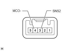
1.76,1.229 2.01,0.458 2.01,0.458 2.198,0.458 true 1.458,1.229 1.188,0.469 1.188,0.469 0.958,0.469 true 2.26,0.385 2.698,0.552 0.438,0.167 10 false SNS2 0.542,0.375 0.958,0.552 0.417,0.177 10 false MCO-

Measure the resistance according to the value(s) in the table below.

Standard Resistance:
Tester Connection Condition Specified Condition
3 (SNS2) - 4 (MCO-) Always Below 1 Ω


Result:
Proceed to
OK
NG


Post-procedure1

c.

None


OK

NG

4.CHECK HARNESS AND CONNECTOR (RADIO RECEIVER ASSEMBLY - TELEPHONE MICROPHONE ASSEMBLY AND TELEPHONE TRANSCEIVER ASSEMBLY)

Pre-procedure1

a.

Disconnect the I13 radio receiver assembly connector.


b.

Disconnect the I55 telephone transceiver assembly connector.


c.

Disconnect the d30 telephone microphone assembly connector.


Procedure1

d.

Measure the resistance according to the value(s) in the table below.

Standard Resistance:
Tester Connection Condition Specified Condition

Click Location & Routing(I13,d30,I55)Location & Routing

Click Connector(I13)Instrument Panel>Instrument Panel Wire / Mobile Wireless Charger Cord / No. 1 Navigation Wire / No. 2 Instrument Panel Wire / No. 5 Instrument Panel Wire / Telephone Computer Wire>Radio & Display Receiver Assembly

Click Connector(d30)Body>No. 1 Roof Wire>Telephone Microphone Assembly RH

Click Connector(I55)Instrument Panel>Instrument Panel Wire / Mobile Wireless Charger Cord / No. 1 Navigation Wire / No. 2 Instrument Panel Wire / No. 5 Instrument Panel Wire / Telephone Computer Wire>Telematics Transceiver Assembly

I13-25 (SNS2) - d30-3 (SNS2) Always Below 1 Ω
I55-7 (MCI-) - d30-4 (MCO-) Always Below 1 Ω
I13-25 (SNS2) - Body ground Always 10 kΩ or higher
I55-7 (MCI-) - Body ground Always 10 kΩ or higher


Result:
Proceed to
OK
NG


Post-procedure1

e.

None


OK

5.CHECK TELEPHONE TRANSCEIVER ASSEMBLY (MCI-)

NG

REPAIR OR REPLACE HARNESS OR CONNECTOR

5.CHECK TELEPHONE TRANSCEIVER ASSEMBLY (MCI-)
a.
E427105C80
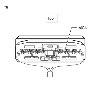
1.583,0.479 1.99,0.76 0.406,0.281 2.24,1.698 2.458,0.948 2.458,0.948 2.635,0.948 true 1.656,0.542 2.135,0.771 0.479,0.229 10 false I55 2.698,0.875 3.156,1.073 0.458,0.198 10 false MCI- 0.146,0.156 0.458,0.354 0.313,0.198 10 false *a
*a Component with harness connected
(Telephone Transceiver Assembly)


Remove the telematics transceiver with the connector(s) still connected.

Click hereAudio / Visual / Telematics>TELEMATICS>TELEMATICS TRANSCEIVER>REMOVAL


b.

Measure the resistance according to the value(s) in the table below.

Standard Resistance:
Tester Connection Condition Specified Condition

Click Location & Routing(I55)Location & Routing

Click Connector(I55)Instrument Panel>Instrument Panel Wire / Mobile Wireless Charger Cord / No. 1 Navigation Wire / No. 2 Instrument Panel Wire / No. 5 Instrument Panel Wire / Telephone Computer Wire>Telematics Transceiver Assembly

I55-7 (MCI-) - Body ground Always Below 1 Ω


Result:
Proceed to
OK
NG


OK

3.INSPECT TELEPHONE MICROPHONE ASSEMBLY (SNS2, MCO-)

NG

REPLACE TELEPHONE TRANSCEIVER ASSEMBLY