MAINTENANCE F33A-FTV DRIVE BELT REMOVAL
CAUTION / NOTICE / HINT
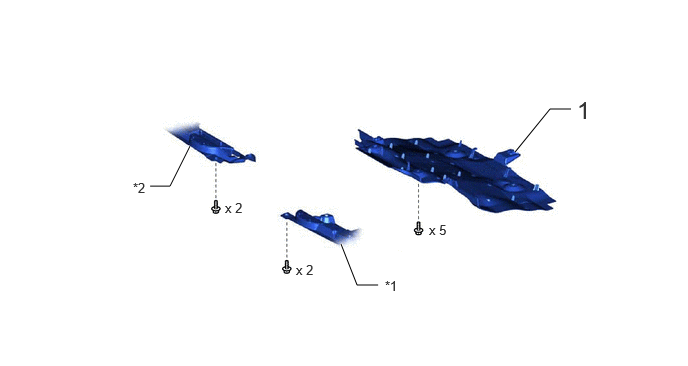
| Procedure | Part Name Code |

|

|

|
|
|---|---|---|---|---|---|
| 1 | NO. 1 ENGINE UNDER COVER ASSEMBLY | 51410 | - | - | - |
| *1 | ENGINE SIDE COVER SUB-ASSEMBLY LH | *2 | ENGINE SIDE COVER SUB-ASSEMBLY RH |
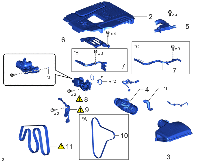
| Procedure | Part Name Code |
|
|
|
|
|---|---|---|---|---|---|
| 2 | NO. 1 ENGINE COVER SUB-ASSEMBLY | 12601B | - | - | - |
| 3 | AIR CLEANER CAP | 17735 | - | - | - |
| 4 | NO. 1 AIR CLEANER HOSE AND INTAKE AIR CONNECTOR | - | - | - | - |
| 5 | ENGINE WIRE | 82121 | - | - | - |
| 6 | INTERCOOLER INSULATOR | 17951 | - | - | - |
| 7 | NO. 2 WATER BY-PASS PIPE | 16278K | - | - | - |
| 8 | INLET COMPRESSOR ELBOW | 17274 | ( ) |
- | - |
| 9 | COOLING FAN WIRE | 16364A | () |
- | - |
| 10 | VISCOUS HEATER V BELT | 88359 | - | - | - |
| 11 | FAN AND GENERATOR V BELT | 16361A | () |
- | - |
| *A | w/ Viscous Heater | *B | w/ EGR System |
| *C | w/o EGR System | - | - |
| *1 | NO. 2 PCV HOSE | *2 | INLET COMPRESSOR GASKET |
| *3 | O-RING | - | - |
| ● | Non-reusable part | - | - |
- CAUTION:
-
·
When the engine is hot, do not touch the high temperature parts of the engine.
·Touching the high temperature parts of the engine may result in burns.
- NOTICE:
-
Do not pour oil in the V-ribbed belt tensioner assembly while there is abnormal fan and generator V belt noise.
PROCEDURE

 51410 1.REMOVE NO. 1 ENGINE UNDER COVER ASSEMBLY
12601B 2.REMOVE NO. 1 ENGINE COVER SUB-ASSEMBLY
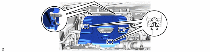
17735 3.REMOVE AIR CLEANER CAP
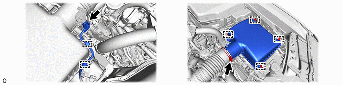
4.REMOVE NO. 1 AIR CLEANER HOSE AND INTAKE AIR CONNECTOR
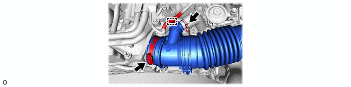
82121 5.DISCONNECT ENGINE WIRE
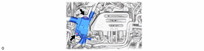
17951 6.REMOVE INTERCOOLER INSULATOR
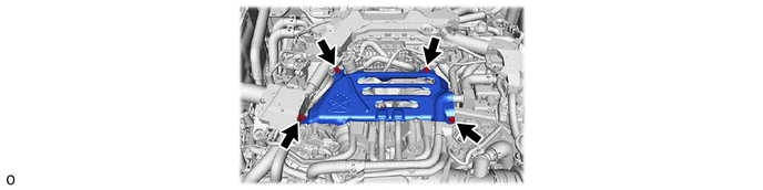
16278K 7.DISCONNECT NO. 2 WATER BY-PASS PIPE
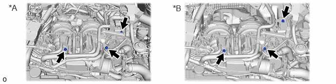
| *A | w/ EGR System | *B | w/o EGR System |
17274 8.REMOVE INLET COMPRESSOR ELBOW
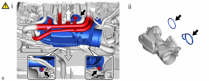

|
Slide Upward |

|
Pull Out |
Remove the 3 bolts, and remove the compressor inlet elbow while sliding the No. 2 water by-pass pipe upward.
- HINT:
-
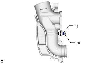 2.552,1.458 2.406,1.458 2.406,1.458 2.208,1.177 true 2.167,1.104 2.365,0.865 2.365,0.865 2.49,0.865 true 2.552,0.813 2.865,0.969 0.313,0.156 10 false *1 2.594,1.385 2.875,1.583 0.281,0.198 10 false *a
*1 O-ring *a Bolt A
-
An O-ring is installed to bolt A to prevent it from accidentally being removed.
Remove the inlet compressor gasket and O-ring from the inlet compressor elbow.
16364A 9.REMOVE COOLING FAN WIRE
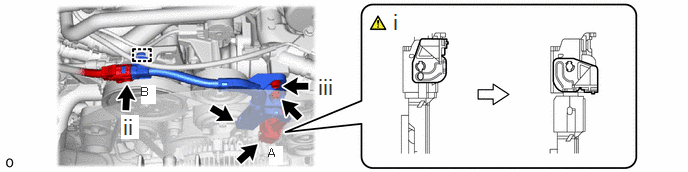
Push the lever down to release the lock and disconnect connector A.
Disconnect the clamp and connector B.
Remove the 2 bolts and cooling fan wire.
88359 10.REMOVE VISCOUS HEATER V BELT (w/ Viscous Heater)
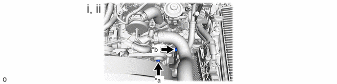
| *a | Fixing Nut | *b | Adjusting Bolt |
Loosen the fixing nut.
Turn the adjusting bolt, loosen the tension of the viscous heater V belt and remove the viscous heater V belt.
16361A 11.REMOVE FAN AND GENERATOR V BELT
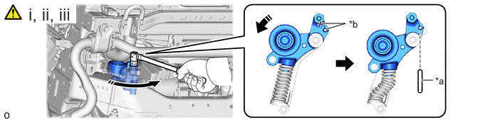
| *a | Hexagon Wrench (5 mm) | *b | Service Hole |

|
Turn in this Direction | - | - |
Turn the hexagonal portion of the V-ribbed belt tensioner assembly counterclockwise to loosen tension.
- NOTICE:
-
·
When working on the V-ribbed belt tensioner assembly, securely insert the tool and operate while paying attention to the rotational direction.
·Do not apply any additional force after the arm stops moving.
Align the service hole of the V-ribbed belt tensioner assembly.
Using a hexagon wrench (5 mm), secure the V-ribbed belt tensioner assembly and remove the fan and generator V belt.