F33A-FTV EMISSION CONTROL UREA PUMP REMOVAL
CAUTION / NOTICE / HINT
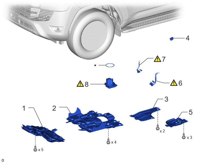
| Procedure | Part Name Code |

|

|

|
|
|---|---|---|---|---|---|
| 1 | NO. 1 ENGINE UNDER COVER ASSEMBLY | 51410 | - | - | - |
| 2 | NO. 2 ENGINE UNDER COVER ASSEMBLY | 51420 | - | - | - |
| 3 | FRAME UNDER COVER ASSEMBLY LH | 51450C | - | - | - |
| 4 | UREA TANK CAP ASSEMBLY | 77830A | - | - | - |
| 5 | UREA TANK PROTECTOR | 77851A | - | - | - |
| 6 | UREA TANK HARNESS | 77885 | ( ) |
- | - |
| 7 | UREA TUBE WITH HEATER ASSEMBLY | 77840A | () |
- | - |
| 8 | UREA PUMP | 77871A | () |
- | - |
| ● | Non-reusable part | - | - |
PROCEDURE

 51410 1.REMOVE NO. 1 ENGINE UNDER COVER ASSEMBLY
51420 2.REMOVE NO. 2 ENGINE UNDER COVER ASSEMBLY
51450C 3.REMOVE FRAME UNDER COVER ASSEMBLY LH
77830A 4.REMOVE UREA TANK CAP ASSEMBLY
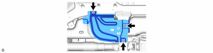
77851A 5.REMOVE UREA TANK PROTECTOR
77885 6.DISCONNECT UREA TANK HARNESS
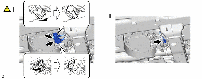
Raise the lever while pushing the lock on the lever and disconnect the 2 connectors from the urea pump.
- NOTICE:
-
·
After disconnecting a connector, make sure that dirt, water and other foreign matter does not contact the connector.
·Put the urea pump connector ends in plastic bags to prevent damage and foreign matter contamination.
Disconnect the connector from the urea tube with heater assembly.
77840A 7.DISCONNECT UREA TUBE WITH HEATER ASSEMBLY
|
|
|
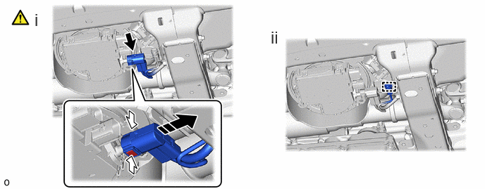
Pinch the retainer of the urea tube connector, and then pull the urea tube connector off of the urea tube with heater assembly.
- NOTICE:
-
·
If there is any solidified urea solution (white solids) on the connection area, clean the solids off with a damp cloth, etc., before disconnecting the connector.
·Be sure to disconnect the urea tube connector by hand.
·Check for foreign matter in the urea pump and around the urea tube connector. Clean if necessary. Foreign matter may damage the O-ring or cause leaks in the seal between the urea pump and urea tube connector.
·Put the urea pump and urea tube connector ends in plastic bags to prevent damage and foreign matter contamination.
Detach the clamp and disconnect the connector from the urea tank sub-assembly.
77871A 8.REMOVE UREA PUMP
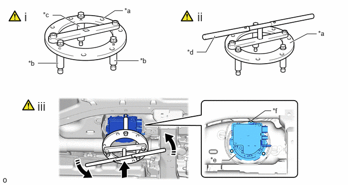
| *a | SST (Fuel Pump Retainer Tool) | *b | SST (Claw A) |
| *c | SST (Claw B) | *d | SST (Handle) |
| *e | Lock Plate | *f | Cutout |
Install SST (urea pump reatainer tool) to SST (clow A) and SST (clow B).
- SST
-
09809-36010 (09809-03010, 09809-03030, 09809-03040, 09809-03050)
09808-14031 (09808-01010)
Install SST (handle) to SST (urea pump retainer tool).
- SST
-
09808-14031
Align the SST (clow B) with the cutout of the lock plate, and loosens the lock plate.
- NOTICE:
-
·
Do not use any tools other than SST, such as screwdriver, etc.
·Make sure to rotate SST (handle) horizontally. If it is rotated at an angle, SST may come off.
·Do not use an impact wrench or turn SST handle with excessive force, as parts may be damaged.
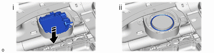
Remove the urea pump and then drain urea solution (AdBlue) into the container.
Remove the gasket.