DOOR / HATCH FRONT DOOR ADJUSTMENT
CAUTION / NOTICE / HINT
The necessary procedures (adjustment, calibration, initialization or registration) that must be performed after parts are removed, installed or replaced during the front door adjustment are shown below.
| Replaced Part or Performed Procedure | Necessary Procedure | Effect/Inoperative Function when Necessary Procedure not Performed | Link |
|---|---|---|---|
| Disconnect cable from negative auxiliary battery terminal | Memorize steering angle neutral point | Parking assist monitor system | ( ) |
| Multi-terrain Monitor system | () |
||
| Panoramic view monitor system | () |
- HINT:
-
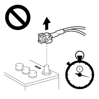
When the cable is disconnected/reconnected to the auxiliary battery terminal, systems temporarily stop operating. However, each system has a function that completes learning the first time the system is used.
-
·
Learning completes when vehicle is driven
Effect/Inoperative Function When Necessary Procedure not Performed Necessary Procedures Link Stop and start system Drive the vehicle until stop and start control is permitted (approximately 5 to 60 minutes) ( )Lighting system (EXT) Cornering lights Drive the vehicle straight ahead at 35 km/h (22 mph) or more for 5 seconds or more. ( )Pre-collision system Lane tracing assist system Lane departure alert system Adaptive high beam system
·Learning completes when vehicle is operated normally
Effect/Inoperative Function when Necessary Procedure not Performed Necessary Procedures Link Power back door system Fully close the back door by hand.
- HINT:
-
Initialization is not necessary if the above procedures are performed while the back door is closed.
( )Air conditioning system After the ignition switch is turned to ON, the servo motor and expansion valve standard position is recognized. -
- HINT:
-
·
Use the same procedure for RHD and LHD vehicles.
·The procedure below is for LHD vehicles.
·Use the same procedure for the RH and LH sides.
·The following procedure is for the LH side.
·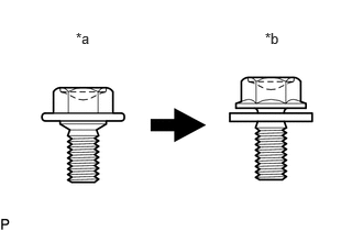 0.719,0.281 1.031,0.438 0.313,0.156 10 false *a 2.51,0.281 2.823,0.438 0.313,0.156 10 false *b
*a Centering Bolt *b Standard Bolt
Centering bolts are used to mount the door hinge to the vehicle body and door. The door cannot be adjusted with the centering bolts on. Substitute the centering bolts for standard bolts when making adjustments.
PROCEDURE

 1. PRECAUTION

|
|
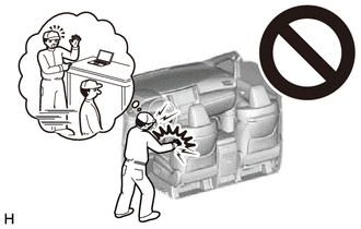
2.DISCONNECT CABLE FROM NEGATIVE AUXILIARY BATTERY TERMINAL
|
|
|
for 1GR-FE:
for V35A-FTS:
for F33A-FTV:
3.INSPECT FRONT DOOR
Check that the clearance measurements of areas "A" to "S" are within the standard ranges.
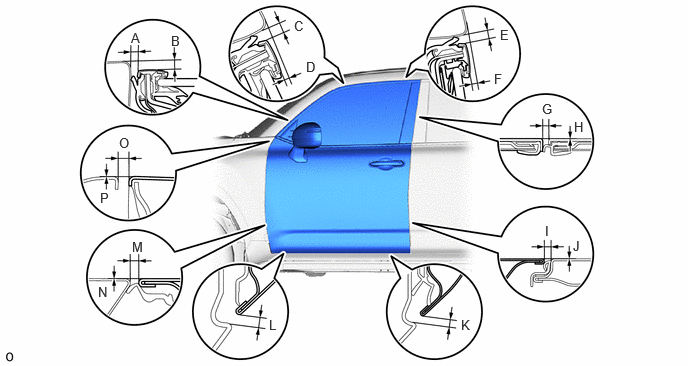
| Area | Measurement | Area | Measurement |
|---|---|---|---|
| A | 2.95 to 6.05 mm (0.1161 to 0.2382 in. | B | 4.55 to 8.25 mm (0.1791 to 0.3248 in.) |
| C | 2.95 to 6.05 mm (0.1161 to 0.2382 in.) | D | 1.35 to 5.05 mm (0.0531 to 0.1988 in.) |
| E | 2.95 to 6.05 mm (0.1161 to 0.2382 in.) | F | 1.25 to 4.95 mm (0.0492 to 0.1949 in.) |
| G | 3.2 to 7.2 mm (0.1260 to 0.2835 in.) | H | -2.0 to 2.0 mm (-0.0787 to 0.0787 in.) |
| I | 3.45 to 6.15 mm (0.1358 to 0.2421 in.) | J | -1.35 to 1.35 mm (-0.0531 to 0.0531 in.) |
| K | 4.3 to 7.7 mm (0.1693 to 0.3031 in.) | L | 4.3 to 7.7 mm (0.1693 to 0.3031 in.) |
| M | 3.6 to 6.0 mm (0.1417 to 0.2362 in.) | N | -1.2 to 1.2 mm (-0.0472 to 0.0472 in.) |
| O | 3.6 to 6.0 mm (0.1417 to 0.2362 in.) | P | -1.2 to 1.2 mm (-0.0472 to 0.0472 in.) |
4.ADJUST FRONT DOOR
- NOTICE:
-
Make sure to turn the ignition switch off when adjusting door lock strikers.
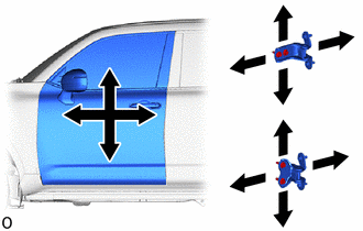
Using SST, loosen the 4 hinge bolts on the vehicle body and adjust the door position.
- SST
-
09812-00010
Using SST, tighten the bolt hinge bolts after the adjustment.
- Torque:
- 26.0 N*m (265 kgf*cm, 19 ft.*lbf)
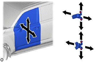
Using SST, loosen the 4 hinge bolts on the door and adjust the door position.
- SST
-
09812-00010
Tighten the 4 hinge bolts on the door after adjustment.
- Torque:
- 21.0 N*m (214 kgf*cm, 15 ft.*lbf)
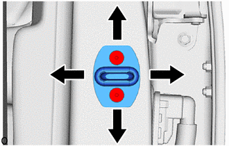
Using a T40 "TORX" socket wrench, slightly loosen the 2 striker mounting screws.
Using a brass bar and a hammer, hit the striker to adjust its position.
Using a T40 "TORX" socket wrench, tighten the 2 striker mounting screws after adjustments.
- Torque:
- 23.0 N*m (235 kgf*cm, 17 ft.*lbf)