Home › Engine / Hybrid System › V35A-FTS (STARTING) › STARTER (w/ Stop And Start System)
RM38G0E _51 Engine / Hybrid System _101526 V35A-FTS STARTING _0470473 STARTER(w/ Stop And Start System) A

V35A-FTS STARTING  STARTER(w/ Stop And Start System)  REASSEMBLY  


CAUTION / NOTICE / HINT
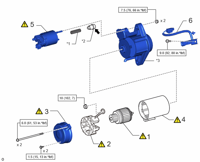
COMPONENTS (REASSEMBLY)
A531426N01
4.25,0.26 5.281,0.448 1.031,0.188 2.083,3.417 2.74,3.635 0.656,0.219 0.938,5.542 1.969,5.74 1.031,0.198 0.719,4.302 1.698,4.542 0.979,0.24 5.635,1.792 6.667,2.01 1.031,0.219 5.188,2.188 5.521,2.188 false 3.24,4.854 3.354,5.177 3.354,5.177 3.542,5.177 false 1.302,0.917 1.469,0.917 1.469,0.917 1.677,1.146 false 6.688,0.75 6.563,0.75 6.563,0.75 6.333,1.156 false 5.802,4.146 6.063,4.313 6.063,4.313 6.229,4.313 false 1.792,3.99 2.063,3.99 2.063,3.99 2.344,4.385 false 2.573,1.583 2.708,1.583 2.708,1.583 2.781,1.167 false 3.104,1.479 3.24,1.479 3.24,1.479 3.354,1.031 false 4.406,4.427 4.76,4.875 4.76,4.875 4.99,4.875 false 5.292,0.344 5.583,0.344 5.583,0.344 5.583,0.708 false 2.75,3.521 3.021,3.521 3.021,3.521 3.021,3.76 false 1.469,5.354 1.469,5.531 false 0.625,4.99 0.625,4.427 0.625,4.427 0.719,4.427 false 6,1.781 6,1.531 false 6.76,0.583 7.042,0.938 0.281,0.354 18 false 6 6.51,4.146 6.792,4.5 0.281,0.354 18 false 4 1.083,0.729 1.365,1.083 0.281,0.354 18 false 5 1.604,3.865 1.885,4.219 0.281,0.354 18 false 3 3.833,5.031 4.115,5.354 0.281,0.323 18 false 2 0.604,5.125 0.969,5.313 0.365,0.188 10 false x 2 1.542,5.344 1.906,5.531 0.365,0.188 10 false x 2 5.75,0.656 6.115,0.844 0.365,0.188 10 false x 2 5.26,4.771 5.677,5.125 0.417,0.354 18 false 1 2.385,1.49 2.698,1.688 0.313,0.198 10 false *1 2.927,1.396 3.24,1.594 0.313,0.198 10 false *2 5.594,2.094 5.906,2.292 0.313,0.198 10 false *3 4.333,0.292 5.344,0.448 1.01,0.156 8 false 7.5 (76, 66 in.*lbf) 2.125,3.458 3.479,3.615 1.354,0.156 8 false 10 (102, 7) 1,5.573 2.115,5.74 1.115,0.167 8 false 1.5 (15, 13 in.*lbf) 0.771,4.354 1.719,4.542 0.948,0.188 8 false 6.0 (61, 53 in.*lbf) 5.719,1.833 6.76,2.094 1.042,0.26 8 false 9.0 (92, 80 in.*lbf)

Procedure Part Name Code
Z101186

Z101188

Z101187

1 STARTER ARMATURE ASSEMBLY 28160 (Click here) - -
2 STARTER BRUSH HOLDER ASSEMBLY 28140 (Click here) - -
3 STARTER COMMUTATOR END FRAME ASSEMBLY - (Click here) - -
4 STARTER YOKE ASSEMBLY 28120 (Click here) - -
5 REPAIR SERVICE STARTER KIT 28226B (Click here) - -
6 HARNESS - - - -

*1 RETURN SPRING *2 PLUNGER
*3 NO. 2 REPAIR SERVICE STARTER KIT - -
V100146

N*m (kgf*cm, ft.*lbf): Specified torque
V100135

High-temperature Grease

PROCEDURE

Hide 28160 1.INSTALL STARTER ARMATURE ASSEMBLY

a.
A531427N01
2.052,0.167 2.333,0.521 0.281,0.354 18 false i

i.

Install the starter armature assembly to the starter yoke assembly.

NOTICE:

The magnet of the starter yoke assembly may attract the starter armature assembly when the starter armature assembly is installed, causing the magnet to break.


Hide 28140 2.INSTALL STARTER BRUSH HOLDER ASSEMBLY

a.

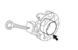
When installing a new part:

Z101186

NOTICE:
A512595

Do not remove the retainer.


A531428C01
0.448,0.542 0.615,0.292 0.615,0.292 0.698,0.292 false 1.5,0.844 1.583,1.344 1.583,1.344 1.75,1.344 false 3.167,1.417 3.333,1.417 3.333,1.417 3.417,1 true 5.417,1.177 5.5,1.594 5.5,1.594 5.667,1.594 false 0.406,0.073 0.688,0.427 0.281,0.354 18 false i 2.969,0.063 3.521,0.417 0.552,0.354 18 false ii 5.479,0.052 6.313,0.406 0.833,0.354 18 false iii 0.75,0.198 1.063,0.396 0.313,0.198 10 false *1 1.833,1.25 2.146,1.448 0.313,0.198 10 false *2 2.979,1.323 3.292,1.521 0.313,0.198 10 false *a 5.708,1.49 6.021,1.688 0.313,0.198 10 false *a
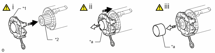
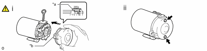
*1 Starter Brush Holder Assembly *2 Starter Armature Assembly
*a Retainer - -
V113147

Push Starter Brush Holder Assembly in this Direction
V113148

Push out Retainer in this Direction


i.

With the retainer installed, push the starter brush holder assembly onto the starter armature assembly.

NOTICE:

Be careful not to damage the brushes when pushing the starter brush holder assembly in place.


HINT:

Install the starter brush holder assembly as shown in the illustration, as the installation direction is fixed.


ii.

Push the starter brush holder assembly onto the starter armature assembly while pushing out the retainer with the end of the starter armature assembly.


iii.

Push the starter brush holder assembly onto the starter armature assembly until the retainer is completely pushed out.


b.

When reinstalling:

A531429C01
1.917,2.115 1.802,1.375 1.802,1.375 2.031,1.625 true 1.042,2.073 0.594,1.74 0.594,1.74 1.042,1.604 true 0.438,0.615 0.646,0.708 false 0.656,1.115 0.885,1.125 false 0.563,2.365 0.833,2.542 false 0.354,2.719 0.594,2.896 false 1.26,1.333 1.438,0.896 1.438,0.896 1.625,0.896 false 2.75,0.698 3.01,0.667 false 2.479,1.042 2.781,0.958 false 1.948,2.667 2.177,2.667 false 2.177,3.042 1.885,3.042 false 2.49,2.281 2.323,2.115 false 5.51,0.917 5.833,0.833 false 4.729,0.594 4.833,0.344 false 4.51,1.802 4.802,1.802 false 3.583,3.25 3.333,3.25 false 4.667,2.917 4.833,3.333 false 5.917,2.583 6.073,2.198 6.073,2.198 6.083,2.583 true 5.917,3.115 6.083,3.417 6.083,3.417 6.083,3.115 true 1.417,3.833 1.604,4.083 false 2.198,4.229 1.917,3.74 true 1.781,4.583 1.365,4.969 1.365,4.969 1.781,4.333 true 5.188,4.167 5,3.917 false 0.26,0.521 0.573,0.719 0.313,0.198 10 false *a 0.479,1.021 0.792,1.219 0.313,0.198 10 false *b 0.375,1.646 0.688,1.844 0.313,0.198 10 false *c 0.406,2.24 0.719,2.438 0.313,0.198 10 false *b 0.167,2.604 0.479,2.802 0.313,0.198 10 false *a 1.698,1.156 2.01,1.354 0.313,0.198 10 false *c 1.688,0.823 2,1.021 0.313,0.198 10 false *e 2.719,1.188 3.031,1.385 0.313,0.198 10 false *f 3.042,0.552 3.354,0.75 0.313,0.198 10 false *a 2.823,0.854 3.135,1.052 0.313,0.198 10 false *b 1.76,2.594 2.073,2.792 0.313,0.198 10 false *b 1.698,2.958 2.01,3.156 0.313,0.198 10 false *a 0.677,0.115 0.958,0.469 0.281,0.354 18 false i 4.479,0.083 5.031,0.438 0.552,0.354 18 false ii 3.51,2.042 3.917,2.417 0.406,0.375 18 false iii 5.406,2.042 5.958,2.396 0.552,0.354 18 false iv 0.833,3.813 1.104,4.167 0.271,0.354 18 false v 4.281,3.729 4.833,4.083 0.552,0.354 18 false vi 2.521,2.302 2.833,2.5 0.313,0.198 10 false *d 5.875,0.708 6.188,0.906 0.313,0.198 10 false *c 5.385,0.156 5.698,0.354 0.313,0.198 10 false *h 6.104,1.177 6.479,1.375 0.375,0.198 10 false *g 4.865,0.198 5.177,0.396 0.313,0.198 10 false *a 4.375,1.729 4.688,1.927 0.313,0.198 10 false *i 3.167,3.167 3.479,3.365 0.313,0.198 10 false *e 4.865,3.365 5.177,3.563 0.313,0.198 10 false *f 6.115,2.052 6.427,2.25 0.313,0.198 10 false *i 6.104,3.417 6.417,3.615 0.313,0.198 10 false *i 1.208,3.688 1.521,3.885 0.313,0.198 10 false *1 1.75,3.625 2.063,3.823 0.313,0.198 10 false *2 1.208,4.906 1.521,5.104 0.313,0.198 10 false *j 4.813,3.844 5.125,4.042 0.313,0.198 10 false *1
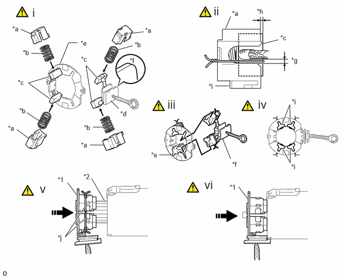
*1 Starter Brush Holder Assembly *2 Starter Armature Assembly
*a Holder Box *b Spring
*c Brush *d Rubber Part
*e Holder Plate *f Rounded Corner of Lead Wire Rubber Part
*g Range for Wire Used to Fix Brush *h 1 mm or less
*i Claw of the Holder Box *j Assembly in this Direction Wire
V113147

Push Starter Brush Holder Assembly in this Direction - -


i.

Set the spring inside the holder box. Then, push the brush inside the holder box in the orientation shown in the illustration.

NOTICE:

Install the holder boxes so the rounded corner of the rubber portion of the lead wire faces the holder plate.


HINT:

Install the holder boxes with their claws facing the holder plate.


ii.

With the brush pushed inside, use wire or similar material to fix the brush in the position shown in the illustration.

NOTICE:
·

When fixing the brush in place using wire or similar material, be careful not to damage the brush.

·

Fix the brush in place so that it protrudes from the holder box by 1 mm or less.


iii.

Insert the claw of the holder box into the holder plate to fix the holder box in place.

NOTICE:

Install the holder boxes so the rounded corner of the rubber portion of the lead wire faces the holder plate.


iv.

Check that the 4 claws of the holder boxes are fixed to the holder plate.


v.

Push the starter brush holder assembly onto the starter armature assembly, but leave enough room to remove the wire or similar material.


vi.

Remove the 4 pieces of wire or similar material and then push the starter brush holder assembly all the way onto the starter armature assembly.

NOTICE:

When removing the wire or similar material, be careful not to damage the brush.


Hide 3.INSTALL STARTER COMMUTATOR END FRAME ASSEMBLY
a.
A531430C01
2.49,0.302 2.354,0.156 2.354,0.156 1.99,0.156 true 2.146,1.01 1.51,1.615 1.51,1.615 1.198,1.615 true 1.813,0.063 2.125,0.26 0.313,0.198 10 false *a 1.021,1.521 1.333,1.719 0.313,0.198 10 false *b 0.406,0.146 0.688,0.5 0.281,0.354 18 false i 4.271,0.115 4.552,0.469 0.281,0.354 18 false ii
*a Lead Wire Rubber *b Cutout


i.

Install the starter commutator end frame assembly to the starter yoke assembly.

NOTICE:

Align the lead wire rubber of the starter yoke assembly with the cutout of the starter commutator end frame assembly.


ii.

Install the 2 screws.

Torque:
1.5 N*m (15 kgf*cm, 13 in.*lbf)


Hide 28120 4.INSTALL STARTER YOKE ASSEMBLY

a.
A531423N02
2.229,0.219 2.51,0.573 0.281,0.354 18 false i

i.

Using a T25 "TORX" socket wrench, install the 2 through bolts.

Torque:
6.0 N*m (61 kgf*cm, 53 in.*lbf)


Hide 28226B 5.INSTALL REPAIR SERVICE STARTER KIT
a.
A531431C01
1.719,0.615 2.125,0.417 true 2.021,1.01 2.219,1.104 false 1.167,1 1.49,0.958 true 0.771,1.844 1.281,1.844 false 2.875,2.552 3.094,2.281 true 3.167,1.417 1.917,1.417 1.917,1.417 1.865,1.583 true 1.979,1.667 2.073,1.573 2.073,1.573 3.406,1.573 true 2.417,1.917 2.417,2.25 true 4.667,0.667 4.917,0.667 4.917,0.667 5.146,1.198 false 5.063,1.74 5.063,2.323 false 1.667,1.802 1.667,1.635 false 1.021,0.333 1.479,0.531 0.458,0.198 10 false 90° 2.188,0.271 2.5,0.469 0.313,0.198 10 false *d 2.281,1.083 2.594,1.281 0.313,0.198 10 false *4 0.938,0.917 1.25,1.115 0.313,0.198 10 false *b 0.573,1.76 0.885,1.958 0.313,0.198 10 false *1 2.729,2.583 3.042,2.781 0.313,0.198 10 false *4 1.604,1.813 1.917,2.01 0.313,0.198 10 false *a 3.479,1.479 3.792,1.677 0.313,0.198 10 false *c 3.208,1.333 3.521,1.531 0.313,0.198 10 false *2 2.354,2.292 2.667,2.49 0.313,0.198 10 false *3 4.5,0.583 4.813,0.781 0.313,0.198 10 false *e 5.01,2.406 5.323,2.604 0.313,0.198 10 false *f 0.344,0.188 0.823,0.563 0.479,0.375 18 false i, ii 4,0.49 4.552,0.844 0.552,0.354 18 false iii
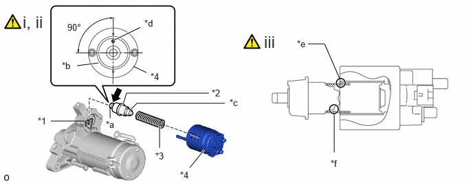
*1 Pinion Drive Lever *2 Plunger
*3 Return Spring *4 Magnet Switch
*a Hook *b Plunger Cover
*c Protrusion *d Ventilation Hole
*e Caution area: make sure to install straight *f Plunger Prodruding Part
V100135

High-temperature Grease - -


i.

Apply high-temperature grease to the plunger as shown in the illustration.


ii.

Hang the hook of the plunger on the pinion drive lever and install the magnet switch.

HINT:

Install the plunger cover so that the ventilation hole is positioned as shown in the illustration.


iii.

Make sure the return spring is not resting on the protrusion of the plunger or pushed between the magnet switch and plunger.
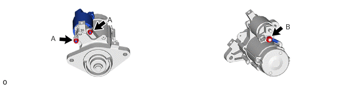


b.
A512547N01
1.042,0.708 1.198,0.906 0.156,0.198 10 false A 2.198,0.323 2.354,0.521 0.156,0.198 10 true A 5.833,0.469 5.99,0.667 0.156,0.198 10 false B

Torque:
Nut A : 7.5 N*m (76 kgf*cm, 66 in.*lbf)
Nut B : 10 N*m (102 kgf*cm, 7 ft.*lbf)


Hide 6.INSTALL HARNESS

Torque:
9.0 N*m (92 kgf*cm, 80 in.*lbf)