1HZ ENGINE CONTROL ECD SYSTEM 22 Engine Coolant Temperature Sensor Circuit Malfunction
DESCRIPTION
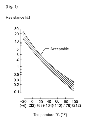
The engine coolant temperature sensor detects the coolant temperature.
A thermistor built into the sensor changes the resistance value according to the coolant temperature. The lower the coolant temperature, the greater the thermistor resistance value, and the higher the coolant temperature, the lower the thermistor resistance value (see Fig. 1).
The engine coolant temperature sensor is connected to the emission control ECU (see below). The 5 V power source voltage in the emission control ECU is applied to the engine coolant temperature sensor from terminal THW via resistor R. That is, resistor R and the engine coolant temperature sensor are connected in series. When the resistance value of the engine coolant temperature sensor changes in accordance with changes in the coolant temperature, the potential at the terminal THW also changes. Based on this signal, the emission control ECU increases the fuel injection volume to improve driveability during cold engine operation.
| DTC No. | Detection Item | DTC Detection Condition | Trouble Area | Warning Indicate | Memory |
|---|---|---|---|---|---|
| 22 | Engine Coolant Temperature Sensor Circuit Malfunction | Open or short in engine coolant temperature sensor circuit for 0.5 seconds or more |
·
Open or short in engine coolant temperature sensor circuit
·
Engine coolant temperature sensor
·
emission control ECU |
Glow Indicator Light Comes on | DTC stored |
WIRING DIAGRAM
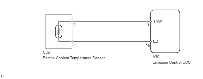
CAUTION / NOTICE / HINT
- HINT:
-
If DTC "22" (engine coolant temperature sensor circuit), "31" (vacuum sensor circuit) and "41" (throttle position sensor circuit) are output simultaneously, the E2 circuit (sensor ground) in the emission control ECU may be open.
PROCEDURE
Turn the ignition switch to ON.
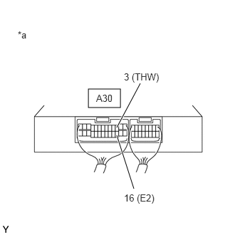
| *a | Component with harness connected (to Emission Control ECU) |
Measure the voltage according to the value(s) in thetable below.
- Standard Voltage:
-
Tester Connection Condition Specified Condition A30-3 (THW) - A30-16 (E2) 20°C (68°F) 0.5 to 3.4 V 80°C (176°F) 0.2 to 1.0 V
- Result:
-
Proceed to OK NG
OK
NG
Remove the engine coolant temperature sensor.
Partially immerse the sensor in water and warm up the water.
Measure the resistance according to the value(s) in the table below.
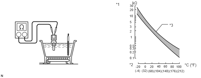
| *1 | Resistance | *2 | Temperature |
| *3 | Acceptable Range | - | - |
- Standard Resistance:
-
Tester Connection Condition Specified Condition 1 - 2 20°C (68°F) 2.21 to 2.69 kΩ 80°C (176°F) 0.29 to 0.354 kΩ
- NOTICE:
-
When checking the sensor in water, keep the terminals dry. After the check, wipe the sensor dry.
- Result:
-
Proceed to OK NG
OK
NG
Disconnect the engine coolant temperature sensor connector.
Disconnect the emission control ECU connector.
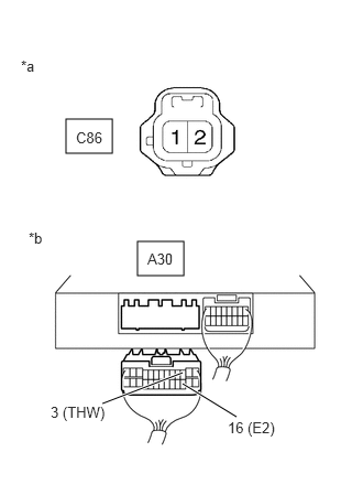
| *a | Front view of wire harness connector (to Engine Coolant Temperature Sensor) |
| *b | Rear view of wire harness connector (to Emission Control ECU) |
Measure the resistance according to the value(s) in the table below.
- Standard Resistance:
-
Tester Connection Condition Specified Condition C86-2 - A30-3 (THW) Always Below 1 Ω C86-1 - A30-16 (E2) Always Below 1 Ω C86-2 or A30-3 (THW) - Body ground Always 10 kΩ or higher C86-1 or A30-16 (E2) - Body ground Always 10 kΩ or higher
- Result:
-
Proceed to OK NG
OK
NG