Home › Engine / Hybrid System › 1HZ (ENGINE CONTROL) › ECD SYSTEM
RM25T0E _51 Engine / Hybrid System _029759 1HZ ENGINE CONTROL _0135351 ECD SYSTEM C

1HZ ENGINE CONTROL  ECD SYSTEM  71  EGR System Malfunction  


DESCRIPTION

The EGR system recirculates exhaust gas, which is controlled to the proper quantity to suit driving conditions, into the intake air mixture to slow down combustion, reduce the combustion temperature and reduce NOx emissions.

The EGR valve lift varies in accordance with the vacuum which is regulated by the E-VRV for EGR as operated by the emission control ECU.

Under the following conditions, EGR is cut to maintain driveability.

·

Before the engine is warmed up

·

During deceleration

·

Light engine load (amount of intake air very small)

·

Engine speed over 4000 rpm


DTC No. Detection Item DTC Detection Condition Trouble Area Warning Indicate Memory
71 EGR System Malfunction When abnormal feedback values have been obtained during EGR control operation (2 trip detection)
·

Vacuum pump

·

Open or short in VSV for EGR cut circuit

·

Open or short in E-VRV for EGR circuit

·

E-VRV for EGR

·

VSV for EGR cut

·

EGR valve assembly

·

Emission Control ECU


Glow Indicator Light Comes on DTC stored

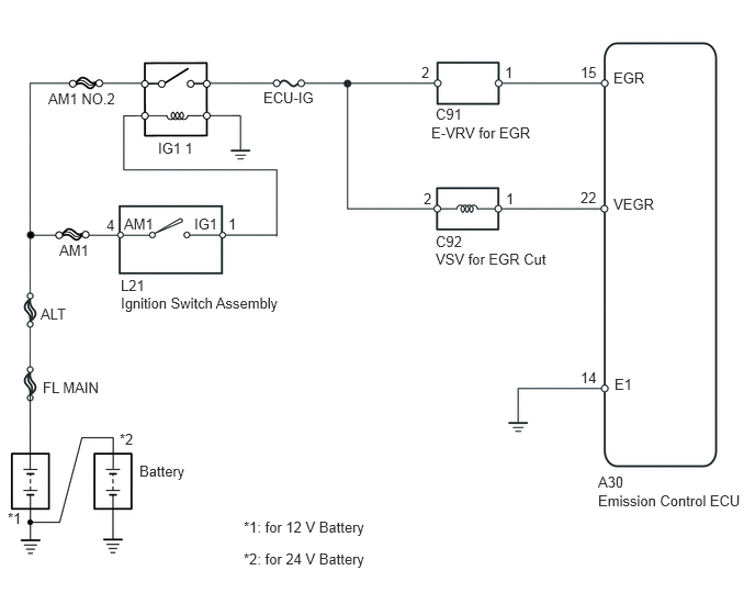
WIRING DIAGRAM

A225220E02
1.01,2.052 1.156,2.229 0.146,0.177 10 false 4 4,0.604 4.104,0.781 0.104,0.177 10 false 2 1.177,2.042 1.531,2.219 0.354,0.177 10 false AM1 1.146,2.625 1.458,2.802 0.313,0.177 10 false L21 1.146,2.792 2.948,3.031 1.802,0.24 10 false Ignition Switch Assembly 4.135,1 4.552,1.188 0.417,0.188 10 false C91 4.094,1.177 5.198,1.354 1.104,0.177 10 false E-VRV for EGR 4.021,1.802 4.229,1.979 0.208,0.177 10 false 2 4.135,2.208 4.521,2.385 0.385,0.177 10 false C92 4.135,2.375 5.229,2.552 1.094,0.177 10 false VSV for EGR Cut 5.51,0.604 5.688,0.781 0.177,0.177 10 false 15 5.823,0.656 6.146,0.833 0.323,0.177 10 false EGR 5.51,1.792 5.688,1.969 0.177,0.177 10 false 22 5.823,1.854 6.229,2.031 0.406,0.177 10 false VEGR 5.51,3.5 5.688,3.677 0.177,0.177 10 false 14 5.833,3.563 6.021,3.74 0.188,0.177 10 false E1 5.677,4.49 6.01,4.677 0.333,0.188 10 false A30 5.677,4.667 7.156,4.875 1.479,0.208 10 false Emission Control ECU 0.563,2.292 1.031,2.479 0.469,0.188 10 false AM1 2.5,0.844 3.063,1.021 0.563,0.177 10 false ECU-IG 1.5,1.323 1.948,1.51 0.448,0.188 10 false IG1 1 0.458,0.854 1.177,1.021 0.719,0.167 10 false AM1 NO.2 0.385,2.896 0.667,3.083 0.281,0.188 10 false ALT 0.406,3.594 0.99,3.75 0.583,0.156 10 false FL MAIN 1.323,4.385 1.802,4.552 0.479,0.167 10 false Battery 0.073,4.833 0.24,4.979 0.167,0.146 10 false *1 1.135,4.083 1.313,4.229 0.177,0.146 10 false *2 2.313,4.917 3.594,5.115 1.281,0.198 10 false *1: for 12 V Battery 2.313,5.219 3.594,5.417 1.281,0.198 10 false *2: for 24 V Battery 2.167,2.042 2.281,2.229 0.115,0.188 10 false 1 1.844,2.042 2.135,2.219 0.292,0.177 10 false IG1 4.792,0.604 4.896,0.781 0.104,0.177 10 false 1 4.802,1.802 4.927,1.979 0.125,0.177 10 false 1

PROCEDURE

1.CHECK VACUUM PUMP ASSEMBLY
a.

Check the negative pressure of the vacuum pump.

Standard:

More than 86.7 kPa (650 mmHg, 26 in.Hg).


Result:
Proceed to
OK
NG


OK

2.CHECK VACUUM HOSES

NG

REPLACE VACUUM PUMP ASSEMBLY

2.CHECK VACUUM HOSES
a.

Check the vacuum hoses.

OK:

The hoses are not damaged and are securely connected.


Result:
Proceed to
OK
NG


OK

3.INSPECT EGR SYSTEM

NG

REPAIR OR REPLACE VACUUM HOSE

3.INSPECT EGR SYSTEM
a.

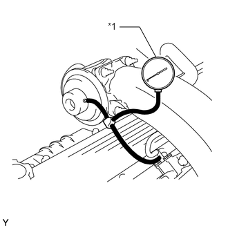
Using a 3-way connector, connect a vacuum gauge to the hose between the VSV for EGR cut and EGR valve.


b.

Warm up the engine to above 80°C (176°F).

c.
A190106C01
2.354,0.865 2.104,0.406 false 2.104,0.406 1.802,0.406 false 1.625,0.313 1.948,0.688 0.323,0.375 10 false *1
*1 Vacuum Gauge


Check the vacuum when the accelerator pedal is fully depressed after the engine speed reaches 1500 rpm.

Result:
Vacuum Gauge Condition Proceed to
Changes from above 28 kPa (210 mmHg, 8.3 in.Hg) to 0 kPa (0 mmHg, 0 in.Hg) A
Stays at 0 kPa (0 mmHg, 0 in.Hg), or stays above 28 kPa (210 mmHg, 8.3 in.Hg) B


B

4.INSPECT VACUUM SWITCHING VALVE (for EGR Cut)

A

11.CHECK EGR VALVE ASSEMBLY
4.INSPECT VACUUM SWITCHING VALVE (for EGR Cut)
a.

Disconnect the emission control ECU connector.


b.

Turn the ignition switch to ON.


c.
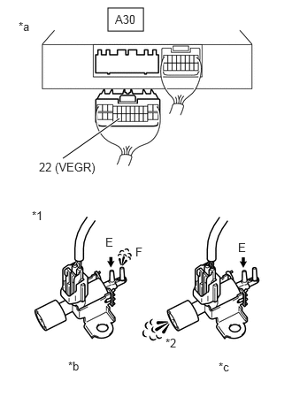
A311444C02
1.271,0.094 1.688,0.365 0.417,0.271 0.74,1.865 1.406,1.396 true 1.24,2.771 1.552,2.969 0.313,0.198 10 false E 0.219,0.229 0.531,0.427 0.313,0.198 10 false *a 0.802,4.229 1.115,4.427 0.313,0.198 10 false *b 2.573,4.24 2.885,4.438 0.313,0.198 10 false *c 2.802,2.833 3.115,3.031 0.313,0.198 10 false E 1.594,2.885 1.906,3.083 0.313,0.198 10 false F 0.375,2.458 0.688,2.656 0.313,0.198 10 false *1 1.948,3.958 2.26,4.156 0.313,0.198 10 false *2 0.458,1.885 1.833,2.083 1.375,0.198 10 false 22 (VEGR) 1.354,0.146 1.719,0.354 0.365,0.208 10 false A30
*1 VSV for EGR Cut
*2 Air Filter
*a Rear view of wire harness connector
(to Emission Control ECU)
*b VSV: ON
*c VSV: OFF


Check the VSV for EGR cut operation.

OK:
Condition Specified Condition
A30-22 (VEGR) and body ground are connected, VSV is ON Air from pipe E flows out through pipe F
A30-22 (VEGR) and body ground are not connected, VSV is OFF Air from pipe E flows out through air filter


Result:
Proceed to
OK
NG


NG

5.INSPECT VACUUM SWITCHING VALVE (for EGR Cut)

OK

7.INSPECT EMISSION CONTROL ECU (EGR VOLTAGE)
5.INSPECT VACUUM SWITCHING VALVE (for EGR Cut)
a.

Disconnect the VSV for EGR cut connector.

b.
A190587C01
0.448,0.656 1.156,0.802 0.708,0.146 10 false *1 2.563,2.76 3,3.167 0.438,0.406 10 false *2
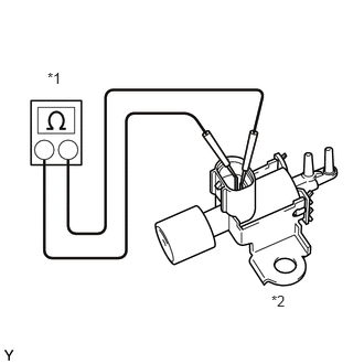
*1 Ohmmeter
*2 VSV for EGR Cut


Measure the resistance according to the value(s) in the table below.

Standard Resistance:
Tester Connection Condition Specified Condition
1 - 2 20°C (68°F) 33 to 39 Ω*1
135 to 155 Ω*2


*1: for 12 V battery

*2: for 24 V battery


c.
A311445C02
0.208,0.646 0.521,0.844 0.313,0.198 10 false *1 0.406,3.448 0.719,3.646 0.313,0.198 10 false *2 2.74,0.104 3.198,0.302 0.458,0.198 10 false Air 2.99,2.427 3.271,2.698 0.281,0.271 10 false Air 2.115,0.604 2.427,0.802 0.313,0.198 10 false E 2.646,3 2.958,3.198 0.313,0.198 10 false E 3.125,3.229 3.344,3.635 0.219,0.406 10 false F
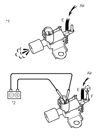
*1 VSV for EGR Cut
*2 Battery


Inspect the VSV for EGR cut operation.

OK:
Tester Connection Condition Specified Condition
1 - 2 No battery voltage applied Air flows from port E to filter
Battery voltage applied across terminals Air flows from port E to F


Result:
Proceed to
OK
NG


OK

6.CHECK HARNESS AND CONNECTOR (VSV FOR EGR CUT - EMISSION ECU)

NG

REPLACE VACUUM SWITCHING VALVE (for EGR Cut)

6.CHECK HARNESS AND CONNECTOR (VSV FOR EGR CUT - EMISSION ECU)
a.

Disconnect the VSV for EGR cut connector.


b.

Disconnect the emission control ECU connector.
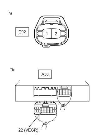

c.
A311446C03
0.521,0.917 0.958,1.208 0.438,0.292 1.281,2.333 1.719,2.625 0.438,0.292 0.979,4.229 1.406,3.729 true 0.281,0.354 0.594,0.552 0.313,0.198 10 false *a 0.344,2.24 0.656,2.438 0.313,0.198 10 false *b 1.385,2.396 1.698,2.594 0.313,0.198 10 false A30 0.615,0.979 1.094,1.26 0.479,0.281 10 false C92 0.615,4.26 1.99,4.458 1.375,0.198 10 false 22 (VEGR)
*a Front view of wire harness connector
(to VSV for EGR Cut)
*b Rear view of wire harness connector
(to Emission Control ECU)


Measure the resistance according to the value(s) in the table below.

Standard Resistance:
Tester Connection Condition Specified Condition
C92-1 - A30-22 (VEGR) Always Below 1 Ω
C92-1 or A30-22 (VEGR) - Body ground Always 10 kΩ or higher


Result:
Proceed to
OK
NG


OK

7.INSPECT EMISSION CONTROL ECU (EGR VOLTAGE)

NG

REPAIR OR REPLACE HARNESS OR CONNECTOR

7.INSPECT EMISSION CONTROL ECU (EGR VOLTAGE)
a.
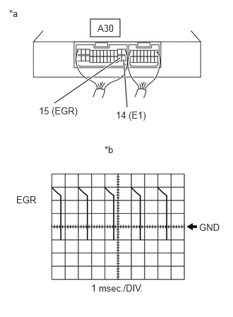
A311447C02
1.333,0.281 1.771,0.542 0.438,0.26 0.802,1.521 1.771,0.854 true 1.875,1.583 1.823,0.875 true 0.135,0.115 0.448,0.313 0.313,0.198 10 false *a 1.542,2.125 1.854,2.323 0.313,0.198 10 false *b 0.24,2.865 0.698,3.063 0.458,0.198 10 false EGR 2.938,3.271 3.344,3.594 0.406,0.323 10 false GND 1.344,4.167 2.531,4.417 1.188,0.25 10 false 1 msec./DIV. 0.573,1.552 1.354,1.896 0.781,0.344 10 false 15 (EGR) 1.708,1.615 2.49,1.958 0.781,0.344 10 false 14 (E1) 1.438,0.333 1.896,0.531 0.458,0.198 10 false A30
*a Component with harness connected
(to Emission Control ECU)
*b EGR Signal Waveform


Measure the voltage according to the value(s) in the table below.

Standard Voltage:
Tester Connection Condition Specified Condition
A30-15 (EGR) - A30-14 (E1) Ignition switch ON 11 to 14 V*1
22 to 28 V*2


*1: for 12 V battery

*2: for 24 V battery


HINT:

When the EGR system is ON (engine speed 1500 rpm), check the waveform between terminals EGR and E1 of the emission control ECU.


Item Content
Terminal EGR and E1
Equipment setting 5 V/DIV., 1 msec./DIV.*1
10 V/DIV., 1 msec./DIV.*2
Condition Engine speed 1500 rpm

*1: for 12 V battery

*2: for 24 V battery


Result:
Proceed to
OK
NG


NG

8.INSPECT VACUUM REGULATING VALVE (for EGR)

OK

11.CHECK EGR VALVE ASSEMBLY
8.INSPECT VACUUM REGULATING VALVE (for EGR)
a.

Disconnect the emission control ECU connector.


b.

Turn the ignition switch to ON.


c.
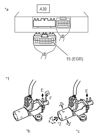
A311448C02
1.25,0.156 1.667,0.427 0.417,0.271 2.281,1.865 1.76,1.406 true 1.938,4.083 2.25,4.281 0.313,0.198 10 false *2 0.188,2.563 0.5,2.76 0.313,0.198 10 false *1 0.156,0.229 0.469,0.427 0.313,0.198 10 false *a 0.885,4.323 1.198,4.521 0.313,0.198 10 false *b 2.563,4.333 2.875,4.531 0.313,0.198 10 false *c 1.375,2.948 1.688,3.146 0.313,0.198 10 false E 2.875,2.979 3.188,3.177 0.313,0.198 10 false E 1.667,3.219 1.979,3.417 0.313,0.198 10 false F 1.333,0.219 1.646,0.417 0.313,0.198 10 false A30 2.229,1.896 3.052,2.219 0.823,0.323 10 false 15 (EGR)
*1 E-VRV for EGR
*2 Air Filter
*a Rear view of wire harness connector
(to Emission Control ECU)
*b E-VRV: ON
*c E-VRV: OFF


Check the E-VRV for EGR operation.

OK:
Condition Specified Condition
A30-15 (EGR) and body ground are connected, VSV is ON Air from pipe E flows out through pipe F
A30-15 (EGR) and body ground are not connected, VSV is OFF Air from pipe E flows out through air filter


Result:
Proceed to
OK
NG


NG

9.INSPECT VACUUM REGULATING VALVE (for EGR)

OK

9.INSPECT VACUUM REGULATING VALVE (for EGR)
a.

Disconnect the E-VRV for EGR connector.
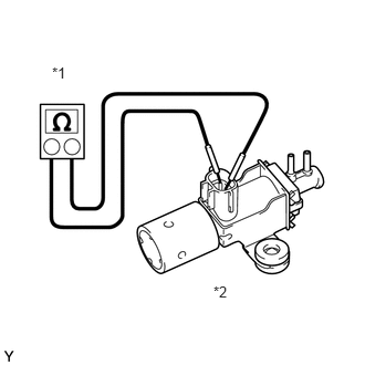

b.
A191457C01
0.49,0.604 1,0.917 0.51,0.313 10 false *1 2.01,2.667 2.49,3.063 0.479,0.396 10 false *2
*1 Ohmmeter
*2 E-VRV for EGR


Measure the resistance according to the value(s) in the table below.

Standard Resistance:
Tester Connection Condition Specified Condition
1 - 2 20°C (68°F) 11 to 13 Ω


Result:
Proceed to
OK
NG


OK

10.CHECK HARNESS AND CONNECTOR (E-VRV FOR EGR - EMISSION ECU)

NG

REPLACE VACUUM REGULATING VALVE (for EGR)

10.CHECK HARNESS AND CONNECTOR (E-VRV FOR EGR - EMISSION ECU)
a.

Disconnect the E-VRV for EGR connector.


b.

Disconnect the emission control ECU connector.
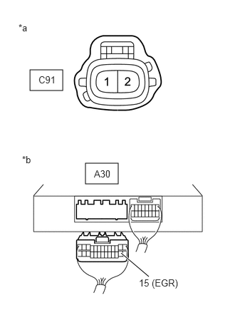

c.
A311449C02
1.25,2.385 1.729,2.688 0.479,0.302 0.438,1.021 0.917,1.323 0.479,0.302 1.771,3.698 2.177,4.042 true 0.271,0.323 0.583,0.521 0.313,0.198 10 false *a 0.323,2.25 0.635,2.448 0.313,0.198 10 false *b 1.375,2.458 1.688,2.656 0.313,0.198 10 false A30 0.563,1.083 0.875,1.281 0.313,0.198 10 false C91 2.031,4.052 2.719,4.396 0.688,0.344 10 false 15 (EGR)
*a Front view of wire harness connector
(to E-VRV for EGR)
*b Rear view of wire harness connector
(to Emission Control ECU)


Measure the resistance according to the value(s) in the table below.

Standard Resistance:
Tester Connection Condition Specified Condition
C91-1 - A30-15 (EGR) Always Below 1 Ω
C91-1 or A30-15 (EGR) - Body ground Always 10 kΩ or higher


Result:
Proceed to
OK
NG


OK

11.CHECK EGR VALVE ASSEMBLY

NG

REPAIR OR REPLACE HARNESS OR CONNECTOR

11.CHECK EGR VALVE ASSEMBLY
a.
A190700C01
1.51,1.646 1.229,1.021 false 1.5,2.615 2.063,2.802 0.563,0.188 10 false *a 1,0.896 1.208,1.083 0.208,0.188 10 false IN 1.948,1.875 2.292,2.063 0.344,0.188 10 false OUT 0.219,0.375 1.125,0.563 0.906,0.188 12 false *1
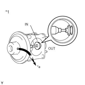
*1 EGR Valve
*a Vacuum


Apply vacuum to the diaphragm chamber and check if air flows between IN and OUT.

Standard:
Vacuum EGR valve condition
Less than 13 kPa (100 mmHg, 3.8 in.Hg) Air does not flow
More than 27 kPa (200 mmHg, 8.0 in.Hg) Air flows


Result:
Proceed to
OK
NG


OK

NG