RM25T0E _54 Brake _029873 BRAKE CONTROL / DYNAMIC CONTROL SYSTEMS _0135612 ANTI-LOCK BRAKE SYSTEM J
BRAKE CONTROL / DYNAMIC CONTROL SYSTEMS ANTI-LOCK BRAKE SYSTEM TC and CG Terminal Circuit
DESCRIPTION
Connecting terminals TC and CG of the DLC3 causes the brake actuator assembly (skid control ECU) to display DTCs through ABS warning light blinking patterns.
WIRING DIAGRAM
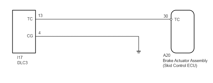
5.49,1.781 6.031,2.063 0.542,0.281 10 false A20 5.479,1.958 7.063,2.583 1.583,0.625 10 false Brake Actuator Assembly (Skid Control ECU) 5.865,0.573 6.469,0.813 0.604,0.24 10 false TC 0.917,0.552 1.313,0.802 0.396,0.25 10 false TC 0.906,1.125 1.552,1.51 0.646,0.385 10 false CG 0.573,1.854 1.427,2.219 0.854,0.365 10 false I17 0.583,2.031 1.552,2.427 0.969,0.396 10 false DLC3 5.5,0.458 5.75,0.667 0.25,0.208 10 false 30 1.281,0.438 1.542,0.667 0.26,0.229 10 false 13 1.292,1.021 1.552,1.25 0.26,0.229 10 false 4
CAUTION / NOTICE / HINT
- NOTICE:
-
·
Before disconnecting the connector, make sure that there are no problems with the connection.
·After disconnecting the connector, make sure that the connector case and terminals are not deformed or corroded.
PROCEDURE
1.CHECK HARNESS AND CONNECTOR (DLC3 - BRAKE ACTUATOR ASSEMBLY)
a.
Turn the ignition switch off.
b.
Disconnect the A20 brake actuator assembly (skid control ECU) connector.
c.
Measure the resistance according to the value(s) in the table below.
- Standard Resistance:
-
Tester Connection Condition Specified Condition I17-4 (CG) - Body ground Always Below 1 Ω I17-13 (TC) - A20-30 (TC) Always Below 1 Ω I17-13 (TC) or A20-30 (TC) - Body ground Always 10 kΩ or higher
- Result:
-
Proceed to OK NG
OK
REPLACE BRAKE ACTUATOR ASSEMBLY
NG
REPAIR OR REPLACE HARNESS AND CONNECTOR