1HZ FUEL FUEL INJECTION PUMP DISASSEMBLY
PROCEDURE

 1. MOUNT PUMP ASSEMBLY TO SST
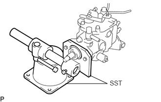
- SST
-
09241-76022
09245-54010
2.REMOVE DRIVE PULLEY SET KEY
Remove the drive pulley set key from the drive shaft.
88031 3.REMOVE IDLE-UP ACTUATOR (w/ Air Conditioning System)
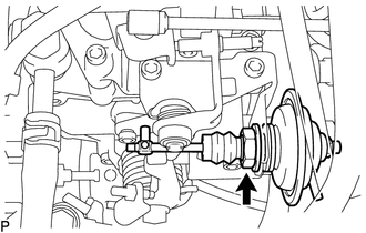
w/ ACSD:
Loosen the nut and remove the idle-up actuator.
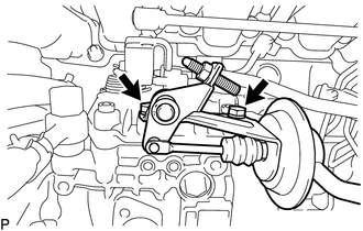
w/o ACSD:
Remove the 2 bolts and idle-up actuator.
23811 4.REMOVE FUEL FILTER TO INJECTION PUMP FUEL PIPE
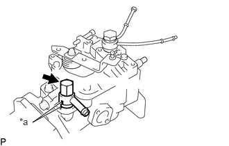
| *a | Matchmark |
Place the matchmarks on the fuel filter to injection pump fuel pipe and governor cover.
Remove the union bolt, 2 gaskets and fuel filter to injection pump fuel pipe.
23770 5.REMOVE NO. 2 NOZZLE LEAKAGE PIPE ASSEMBLY
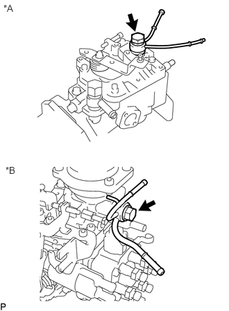
| *A | w/o BACS and HAC |
| *B | w/ BACS and HAC |
Remove the union bolt, 2 gaskets and No. 2 nozzle leakage pipe assembly.
6.REMOVE IDLE-UP LEVER (w/ ACSD)
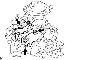
Using a 5 mm hexagon wrench, remove the 3 bolts and idle-up lever.
7.REMOVE THERMO WAX (w/ ACSD)
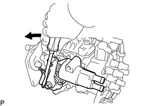
Using a screwdriver, turn the cold starting lever counterclockwise approx. 20°.
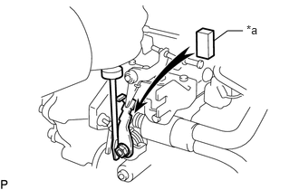
| *a | Metal Plate |
Put a metal plate (thickness of 3.5 to 7.5 mm (0.138 to 0.295 in.)) between the cold starting lever and thermo wax plunger.
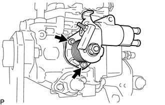
Using a 5 mm hexagon wrench, remove the 2 bolts, thermo wax and O-ring.
22390A 8.REMOVE FUEL CUT SOLENOID
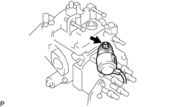
Disconnect the lead wire connector from the bracket.
Disconnect the dust cover from the fuel cut solenoid.
Remove the nut, lead wire and dust cover.
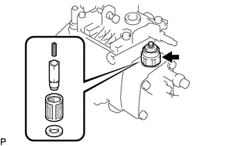
Remove the fuel cut solenoid, O-ring, spring, valve, strainer and wave washer.
9.REMOVE PICKUP SENSOR (w/ TACHOMETER)
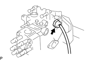
Remove the pickup sensor and O-ring.
10.REMOVE THROTTLE POSITION SENSOR (w/ BACS)
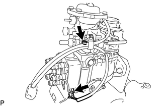
Disconnect the timing control valve connector.
Using a 5 mm hexagon wrench, remove the bolt.
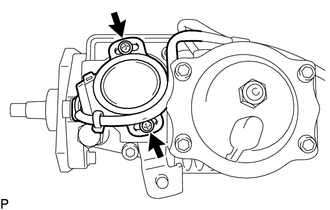
Remove the 2 screws and throttle position sensor.
11.REMOVE THROTTLE POSITION SENSOR BRACKET (w/ BACS)
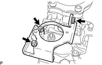
Using a 5 mm hexagon wrench, remove the 3 bolts and throttle position sensor bracket.
22701 12.REMOVE ADJUSTING LEVER (w/o BACS)
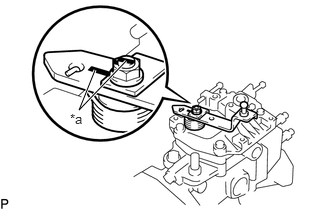
| *a | Matchmark |
Place the matchmarks on the adjusting lever and shaft.
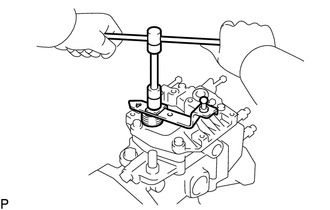
Remove the nut, return spring guide, adjusting lever and return spring.
22701 13.REMOVE ADJUSTING LEVER (w/ BACS)
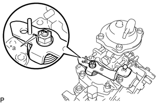
| *a | Matchmark |
Place the matchmarks on the adjusting lever and shaft.
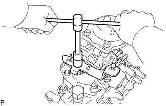
Remove the nut, adjusting lever and return spring.
22703B 14.REMOVE GOVERNOR COVER (w/o BACS)
w/ HAC:
Remove the idle speed adjusting screw.
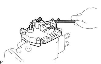
Using a 5 mm hexagon wrench, remove the 4 bolts.
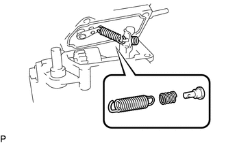
Disconnect the speed control spring from the spring seat, and remove the spring seat, damper spring, speed control spring, the governor cover, adjusting lever shaft assembly and gasket.
22703B 15.REMOVE GOVERNOR COVER (w/ BACS)
Remove the idle speed adjusting screw.
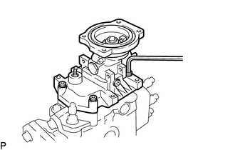
Using a 5 mm hexagon wrench, remove the 4 bolts.
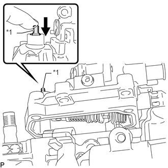
| *1 | Adjusting Lever Shaft |

|
Push |
Push the adjusting lever shaft and remove the governor cover shown in the illustration.
22740 16.REMOVE GOVERNOR ADJUSTING LEVER SHAFT FROM GOVERNOR COVER (w/o BACS)
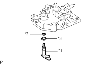
| *1 | Adjusting Lever Shaft |
| *2 | O-ring |
| *3 | Washer |
Remove the following parts from the governor cover.
Adjusting lever shaft, O-ring and washer
O-ring
Washer
22740 17.REMOVE GOVERNOR ADJUSTING LEVER SHAFT FROM GOVERNOR LINK (w/ BACS)
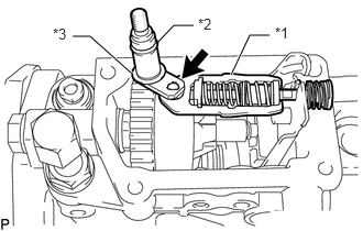
| *1 | Adjusting Lever Shaft |
| *2 | O-ring |
| *3 | Washer |
Remove the following parts from the governor cover.
Adjusting lever shaft
O-ring
Washer
18.DISASSEMBLE HIGH ALTITUDE COMPENSATOR (w/ HAC)
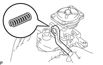
Remove the bolt, gasket and lever control spring.
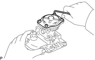
Using a 5 mm hexagon wrench, remove the 4 bolts.
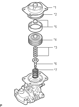
| *1 | Pneumatic Bellows Cover |
| *2 | Gasket |
| *3 | Shims |
| *4 | Pneumatic Bellows |
| *5 | Rubber cap |
| *6 | Push Rod |
| *7 | Pneumatic Bellows Spring |
Remove the following parts:
Pneumatic bellows cover
Gasket
Shims
- NOTICE:
-
Note the number of the shims.
Pneumatic bellows
2 rubber caps
Push rod
Pneumatic bellows spring
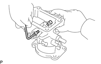
Using a 4 mm hexagon wrench, remove the 2 bolts and 2 gaskets.
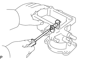
Using a small screwdriver, push out the support pin and remove the control lever.
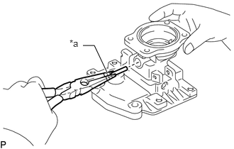
| *a | Protective Tape |
Using needle nose pliers, remove the connecting pin.
- NOTICE:
-
Be careful not to damage the connecting pin.
- HINT:
-
Tape the plier tip before use.
22540 19.REMOVE BOOST COMPENSATOR SUB-ASSEMBLY (w/ BACS)
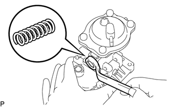
Remove the plug, gasket and lever control spring.
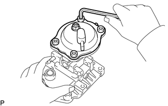
Using a 5 mm hexagon wrench, remove the 4 bolts.
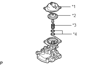
| *1 | Diaphragm Cover |
| *2 | Diaphragm |
| *3 | Spring |
| *4 | Boost Compensator Shim |
Remove the following parts:
Diaphragm cover
Diaphragm
Spring
Boost compensator shim
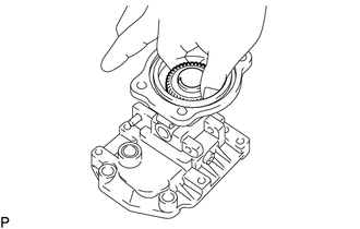
Remove the guide bushing.
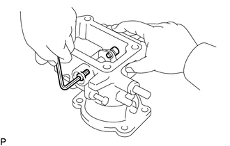
Using a 4 mm hexagon wrench, remove the 2 bolts and 2 gaskets.
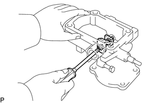
Using a small screwdriver, push out the support pin and remove the control lever.
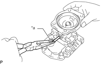
| *a | Protective Tape |
Using needle nose pliers, remove the connecting pin.
- NOTICE:
-
Be careful not to damage the connecting pin.
- HINT:
-
Tape the plier tip before use.
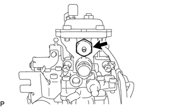
Remove the plug and gasket.
20.REMOVE CAP SEAL
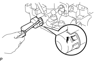
Using a small screwdriver, pry the 4 claws.
Remove the cap seal.
Remove the full load set screw.
21.CHECK FLYWEIGHT HOLDER THRUST CLEARANCE
22420C 22.REMOVE TIMING CONTROL VALVE SUB-ASSEMBLY (w/ BACS)
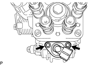
Using a 5 mm hexagon wrench, remove the 2 bolts and timing control valve sub-assembly.
23.REMOVE GOVERNOR SHAFT AND FLYWEIGHT HOLDER
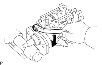
Remove the governor shaft lock nut by turning it clockwise.
- NOTICE:
-
The governor shaft and lock nut have LH threads.
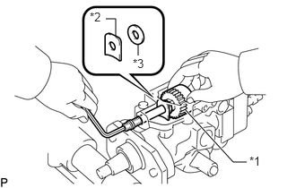
| *1 | Flyweight Holder Assembly |
| *2 | No. 1 Flyweight Washer |
| *3 | Governor Gear Adjusting Washer |
Using a 5 mm hexagon wrench, turn the governor shaft clockwise, and remove the following parts:
Flyweight holder assembly
No. 1 flyweight washer
Governor gear adjusting washer
- HINT:
-
Be careful not to drop the 2 washers into the pump housing.
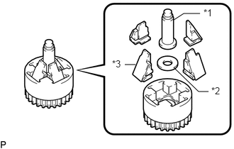
| *1 | Governor Sleeve |
| *2 | No. 2 Flyweight Washer |
| *3 | Flyweight |
Remove the following parts from the flyweight holder.
Governor sleeve
No. 2 flyweight washer
4 flyweights
22811 24.REMOVE INJECTION PUMP STAY
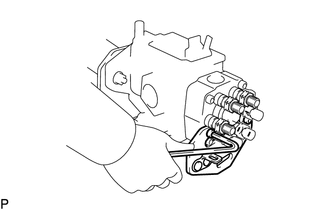
Using a 5 mm hexagon wrench, remove the 3 bolts and injection pump stay.
22176 25.REMOVE DISTRIBUTIVE HEAD PLUG
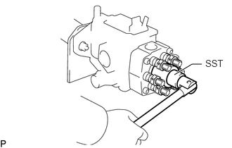
Using SST, remove the distributive head plug.
- SST
-
09260-54012 (09262-54010)
Remove the O-ring from the distributive head plug.
Remove the distributive head plug bolt and gasket.
26.REMOVE DELIVERY VALVE HOLDERS
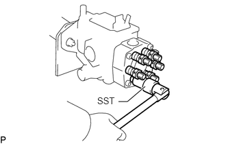
Using SST, remove the delivery valve holders, springs and spring seats.
- SST
-
09260-54012 (09269-54020)
Remove the delivery valves and gaskets.
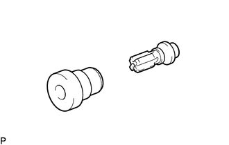
- NOTICE:
-
-
Do not touch the sliding surfaces of the delivery valve with your hand.
- HINT:
-
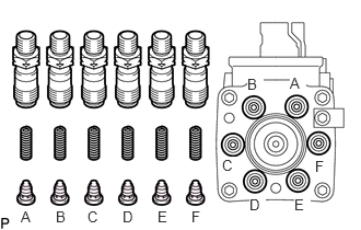 0.198,1.979 0.354,2.177 0.156,0.198 10 false A 0.531,1.979 0.688,2.177 0.156,0.198 10 false B 0.833,1.979 0.99,2.177 0.156,0.198 10 false C 1.167,1.979 1.323,2.177 0.156,0.198 10 false D 1.5,1.979 1.656,2.177 0.156,0.198 10 false E 3,1.5 3.156,1.698 0.156,0.198 10 true F 2.76,0.708 2.917,0.875 0.156,0.167 10 true A 2.354,0.719 2.51,0.896 0.156,0.177 10 true B 2.115,1.49 2.271,1.688 0.156,0.198 10 true C 2.375,1.865 2.531,2.063 0.156,0.198 10 true D 2.802,1.865 2.958,2.063 0.156,0.198 10 true E 1.823,1.979 1.979,2.177 0.156,0.198 10 true F
-
Arrange the delivery valves, springs, spring seats and holders in order.
22140 27.REMOVE DISTRIBUTIVE HEAD
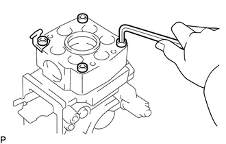
Using a 5 mm hexagon wrench, remove the 4 bolts and wire clip.
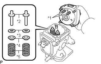
| *1 | Lever Support Spring |
| *2 | Plunger Spring Guide |
| *3 | Plunger Spring Shim |
| *4 | Upper Spring Seat |
| *5 | Plunger Spring |
Remove the distributive head and following parts:
2 lever support springs
2 plunger spring guides
2 plunger spring shims
2 upper spring seats
2 plunger springs
28.REMOVE PUMP PLUNGER
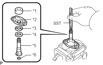
| *1 | Spill Ring |
| *2 | Lower Spring Seat |
| *3 | Upper Plunger Plate |
| *4 | Lower Plunger Plate |
| *5 | Plunger |
| *6 | Shim |
Using SST, remove the pump plunger and plunger adjusting shim together with the following parts:
- SST
-
09260-54012 (09269-54030)
Spill ring
Lower spring seat
Upper plunger plate
Lower plunger plate
- NOTICE:
-
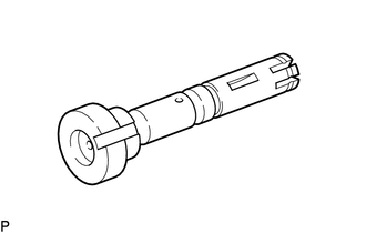
-
Do not touch the sliding surface of the pump plunger with your hand.
29.REMOVE GOVERNOR LINK
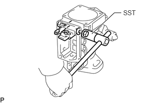
Using SST, remove the 2 support bolts, 2 gaskets and governor link.
- SST
-
09260-54012 (09269-54040)
30.REMOVE FACE CAMPLATE AND COUPLING
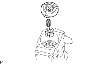
Remove the face camplate, spring and coupling.
31.REMOVE ROLLER RING AND DRIVE SHAFT
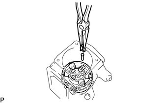
Remove the timer clip and stopper pin.
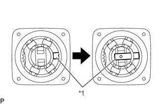
| *1 | Slide Pin |
Push the slide pin toward the inside.
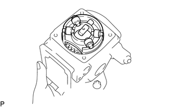
Push the drive shaft, and remove the roller ring, 4 rollers and shim assembly.
- NOTICE:
-
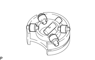
-
·
Be careful not to drop the rollers.
·Do not alter the position or assembly of the rollers.
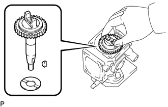
Remove the drive shaft, governor drive gear, 2 joint rubber assemblies, set key and drive shaft washer.
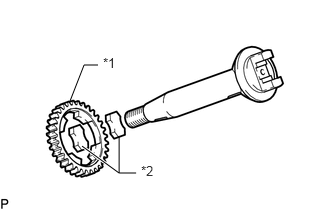
| *1 | Drive Gear |
| *2 | Joint Rubber |
Remove the drive gear and 2 joint rubbers from the drive shaft.
32.REMOVE TIMER
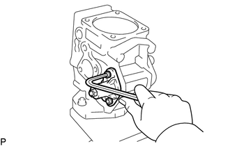
Using a 5 mm hexagon wrench, remove the 4 bolts.
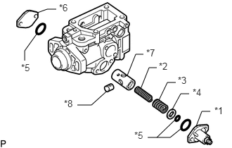
| *1 | LH Timer Cover |
| *2 | Timer Inner Spring |
| *3 | Timer Outer Spring |
| *4 | Timer Shim |
| *5 | O-ring |
| *6 | RH Timer Cover |
| *7 | Timer Piston |
| *8 | Timer Sub-piston |
Remove the distributive head and following parts:
LH timer cover, timer adjusting screw and nut assembly
Timer inner spring
Timer outer spring
Timer shim
O-ring
RH timer cover
O-ring
Timer piston
Timer sub-piston
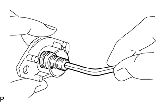
Remove the nut from the LH timer cover.
Using a 5 mm hexagon wrench, remove the timer adjusting screw.
Remove the O-ring from the timer adjusting ring.
33.REMOVE FUEL FEED PUMP
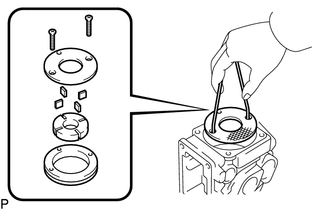
Remove the 2 screws.
Using a piece of wire, remove the feed pump cover.
Remove the feed pump rotor, 4 blades and liner.
- NOTICE:
-
·
Be careful not to interchange the blade positions.
·Be careful not to damage the pump body.
22180 34.REMOVE REGULATOR VALVE
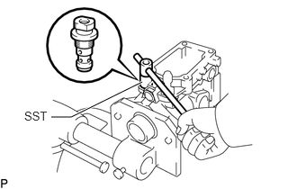
Using SST, remove the regulator valve and 2 O-rings.
- SST
-
09260-54012 (09262-54020)
35.REMOVE FUEL INLET HOLLOW SCREW
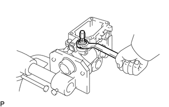
Remove the fuel inlet hollow screw and gasket.
36.REMOVE OIL SEAL
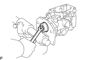
Using a wrench, pry out the oil seal.
- NOTICE:
-
Be careful not to damage the pump body.