1VD-FTV COOLING RADIATOR INSTALLATION
PROCEDURE

 16584 1.INSTALL RADIATOR MOUNTING INSULATOR
Install the 2 radiator mounting insulators and 2 collars.
16400 2.INSTALL RADIATOR ASSEMBLY
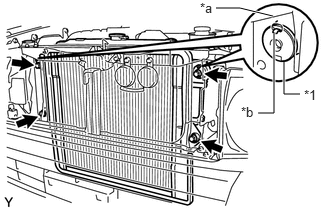
| *1 | Collar |
| *a | Specified Hole |
| *b | Claw |
Place the radiator assembly to the vehicle.
- NOTICE:
-
Do not allow the radiator assembly to interfere with other parts.
Set the collar claws to the specified holes as shown in the illustration.
Install the radiator assembly with the 4 bolts.
- Torque:
- 18 N*m (184 kgf*cm, 13 ft.*lbf)
16572D 3.INSTALL NO. 2 RADIATOR HOSE
Install the No. 2 radiator hose and slide the 2 hose clamps to secure the hose.
16361 4.INSTALL FAN
Install the fan to the fluid coupling assembly with the 4 nuts.
- Torque:
- 8.5 N*m (87 kgf*cm, 75 in.*lbf)
16371 5.INSTALL FAN PULLEY
Install the fan pulley.
16711 6.INSTALL FAN SHROUD
Place the fan shroud together with the fluid coupling fan between the radiator assembly and engine.
- NOTICE:
-
Do not allow the fluid coupling fan to interfere with other parts.
Temporarily install the fluid coupling fan with the 4 nuts, and then tighten the nuts as much as possible by hand.
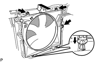
Attach the claws of the fan shroud to the radiator assembly as shown in the illustration.
Install the fan shroud with the 3 bolts.
- Torque:
- 7.8 N*m (80 kgf*cm, 69 in.*lbf)
Install the fan and generator V belt.
Click hereEngine / Hybrid System>1VD-FTV (ENGINE MECHANICAL)>DRIVE BELT>INSTALLATION
Tighten the 4 nuts of the fluid coupling fan.
- Torque:
- 21 N*m (214 kgf*cm, 15 ft.*lbf)
16470 7.INSTALL RADIATOR RESERVOIR ASSEMBLY
Install the radiator reservoir assembly with the 3 bolts.
- Torque:
- 7.8 N*m (80 kgf*cm, 69 in.*lbf)
Connect the No. 2 water by-pass hose to the water inlet and slide the hose clamp to secure the hose.
Connect the No. 1 water by-pass hose to the radiator assembly and slide the hose clamp to secure the hose.
17875 8.INSTALL INTAKE AIR CONNECTOR PIPE
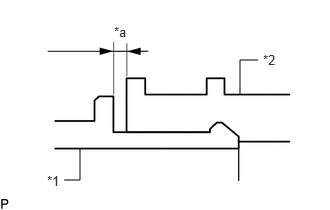
| *1 | Intake Air Connector Pipe |
| *2 | No. 3 Intake Air Connector Pipe |
| *a | 6.0 mm (0.236 in.) or less |
Connect the intake air connector pipe to the No. 3 intake air connector pipe.
- NOTICE:
-
Push the intake air connector pipe onto the No. 3 intake air connector pipe so that the clearance is 6.0 mm (0.236 in.) or less.
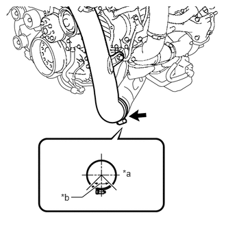
| *a | Left Side |
| *b | 90° |
Install the intake air connector pipe with the 2 bolts.
- Torque:
- 21 N*m (214 kgf*cm, 15 ft.*lbf)
Tighten the hose clamp.
- Torque:
- 5.0 N*m (51 kgf*cm, 44 in.*lbf)
Connect the ventilation hose to the intake air connector pipe and slide the clip to secure the hose.
Attach the wire harness clamp to connect the wire harness to the intake air connector pipe.
Connect the engine coolant temperature sensor connector.
17805 9.INSTALL INTAKE AIR CONNECTOR SUB-ASSEMBLY
| *1 | Intake Air Connector Pipe |
| *2 | Intake Air Connector Sub-assembly |
| *a | 5.0 mm (0.197 in.) or less |
Connect the intake air connector sub-assembly to the intake air connector pipe.
- NOTICE:
-
Push the intake air connector sub-assembly onto the intake air connector pipe so that the clearance is 5.0 mm (0.197 in.) or less.
Install the intake air connector sub-assembly with the 2 bolts.
- Torque:
- 21 N*m (214 kgf*cm, 15 ft.*lbf)
Tighten the hose clamp.
- Torque:
- 5.0 N*m (51 kgf*cm, 44 in.*lbf)
Attach the 2 wire harness clamps to connect the wire harness to the intake air connector sub-assembly.
Connect the air flow meter connector.
10.INSTALL AIR CLEANER CASE SUB-ASSEMBLY
Install the air cleaner case sub-assembly with the 2 bolts and nut.
- Torque:
- 18 N*m (184 kgf*cm, 13 ft.*lbf)
17705 11.INSTALL AIR CLEANER CAP SUB-ASSEMBLY
17881 12.INSTALL NO. 1 AIR CLEANER HOSE
Install the No. 1 air cleaner hose and tighten the 2 hose clamps to secure the hose.
- Torque:
- 2.5 N*m (25 kgf*cm, 22 in.*lbf)
- HINT:
-
Connect the No. 1 air cleaner hose with the arrow marks facing upward and pointing toward the engine.
16571C 13.INSTALL NO. 1 RADIATOR HOSE
Install the No. 1 radiator hose and slide the 2 hose clamps to secure the hose.
14.ADD ENGINE COOLANT
15.INSPECT FOR COOLANT LEAK
53111 16.INSTALL RADIATOR GRILLE
51442 17.INSTALL NO. 2 ENGINE UNDER COVER