AXLE AND DIFFERENTIAL FRONT DIFFERENTIAL CARRIER ASSEMBLY(w/ Differential Lock) DISASSEMBLY
PROCEDURE

 41204D 1.INSPECT RUNOUT OF FRONT DRIVE PINION COMPANION FLANGE SUB-ASSEMBLY
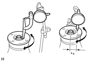
| *a | 30 mm (1.18 in.) |
Using a dial indicator, measure the runout of the companion flange vertically and laterally.
- Maximum Runout:
-
Item Specified Condition Vertical runout 0.10 mm (0.00394 in.) Lateral runout 0.10 mm (0.00394 in.)
If the runout is more than the maximum, replace the companion flange.
2.INSPECT RUNOUT OF DIFFERENTIAL RING GEAR
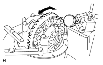
Using a dial indicator, measure the runout of the ring gear.
- Maximum runout:
-
0.10 mm (0.00394 in.)
If the runout is more than the maximum, replace the ring gear with a new one.
3.INSPECT DIFFERENTIAL RING GEAR BACKLASH
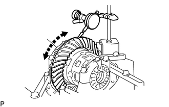
Using a dial indicator, measure the backlash of the differential ring gear.
- Standard backlash:
-
0.13 to 0.18 mm (0.00512 to 0.00708 in.)
- HINT:
-
Measure at 3 or more positions around the circumference of the differential ring gear.
If the backlash is not as specified, adjust the side bearing preload or repair as necessary.
4.INSPECT DRIVE PINION PRELOAD
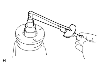
Using a torque wrench, measure the preload of the backlash between the drive pinion and ring gear.
- Standard drive pinion preload (at starting):
-
0.56 to 0.85 N*m (6 to 8 kgf*cm, 5 to 7 in.*lbf)
If necessary, disassemble and inspect the differential.
5.INSPECT TOTAL PRELOAD
Using a torque wrench, measure the total preload with the teeth of the drive pinion and ring gear in contact.
- Standard drive pinion preload (at starting):
-
0.46 to 0.66 N*m (4.7 to 6.7 kgf*cm, 4.1 to 5.8 in.*lbf) + Standard drive pinion preload
If necessary, disassemble and inspect the differential.
41450A 6.REMOVE NO. 2 DIFFERENTIAL LOCK SHIFT ACTUATOR
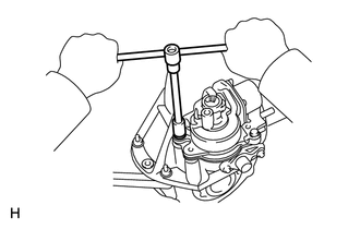
Remove the bolt and No. 2 differential lock shift actuator from the front differential carrier assembly.
Remove the O-ring.
84222D 7.REMOVE NO. 4 TRANSFER INDICATOR SWITCH
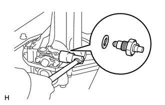
Remove the No. 4 transfer indicator switch and gasket.
41462 8.REMOVE FRONT DIFFERENTIAL LOCK SHIFT FORK SHAFT
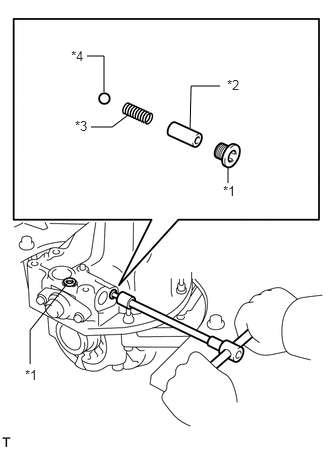
| *1 | Screw Plug |
| *2 | Spring Seat |
| *3 | Compression Spring |
| *4 | Steel Ball |
Using a 6 mm hexagon wrench, remove the 2 screw plugs.
Remove the spring seat, compression spring and steel ball.
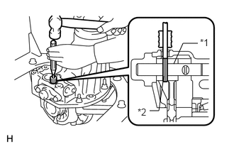
| *1 | Slotted Spring Pin |
| *2 | Front Differential Lock Shift Fork Shaft |
Using a 5 mm pin punch and hammer, tap out the slotted spring pin from the front differential lock shift fork shaft.
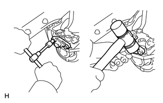
Remove the 2 bolts from the differential lock shaft retainer.
Using a plastic-faced hammer, tap on the differential lock shaft retainer to separate it from the front differential case.
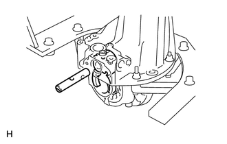
Remove the front differential lock shift fork shaft from the front differential lock shift fork.
41204E 9.REMOVE FRONT DRIVE PINION COMPANION FLANGE NUT
41204D 10.REMOVE FRONT DRIVE PINION COMPANION FLANGE SUB-ASSEMBLY WITH DUST DEFLECTOR
41252A 11.REMOVE FRONT DIFFERENTIAL DUST DEFLECTOR
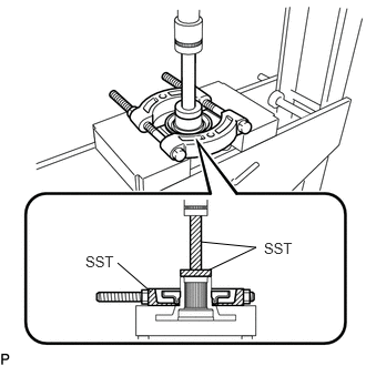
Using SST and press, press out the front differential dust deflector.
- SST
-
09950-00020
09950-60010 (09951-00440)
09950-70010 (09951-07100)
- NOTICE:
-
Do not drop the front drive pinion companion flange sub-assembly.
41101D 12.REMOVE FRONT DIFFERENTIAL CARRIER OIL SEAL
41214C 13.REMOVE FRONT DIFFERENTIAL DRIVE PINION OIL SLINGER
41211B 14.REMOVE FRONT DRIVE PINION REAR TAPERED ROLLER BEARING
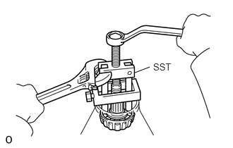
Using SST, remove the front drive pinion rear tapered roller bearing (inner race).
- SST
-
09556-22010
41316A 15.REMOVE FRONT DIFFERENTIAL BEARING ADJUSTING NUT LOCK
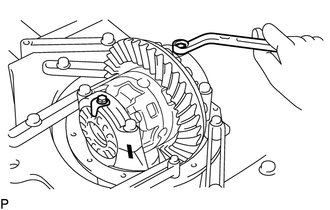
Remove the 2 bolts and 2 front differential bearing adjusting nut locks.
41311 16.REMOVE FRONT DIFFERENTIAL CASE
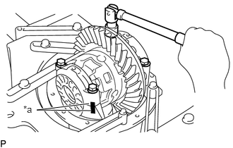
| *a | Matchmark |
Place matchmarks on the bearing caps and differential carrier.
Remove the 4 bolts, 2 bearing caps and 2 front differential bearing adjusting nuts.
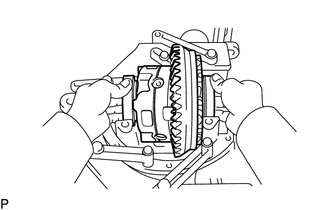
Remove the front differential case from the differential carrier.
- HINT:
-
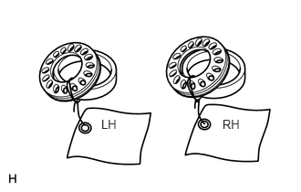 1.156,1.333 1.365,1.5 0.208,0.167 10 LH 2.54,1.329 2.766,1.496 0.226,0.167 10 RH
-
Tag the 2 case bearing outer races to show the locations for reassembly.
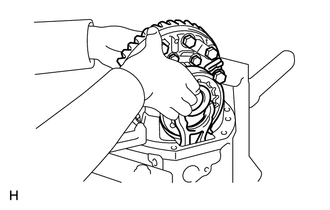
Remove the front differential case with the 2 front differential case bearings (outer race), 2 front differential bearing adjusting nuts and front differential lock sleeve from the differential carrier.
Remove the front differential lock shift fork.
17.REMOVE DIFFERENTIAL DRIVE PINION
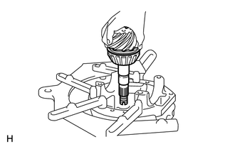
Remove the differential drive pinion from the differential carrier.
41231F 18.REMOVE FRONT DIFFERENTIAL DRIVE PINION BEARING SPACER
41211A 19.REMOVE FRONT DRIVE PINION FRONT TAPERED ROLLER BEARING
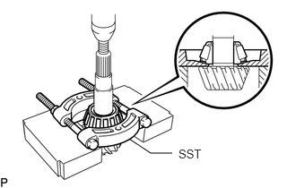
Using SST and a press, press out the front drive pinion front tapered roller bearing (inner race).
- SST
-
09950-00020
If either the differential drive pinion or differential ring gear is damaged, replace them as a set.
20.REMOVE FRONT DIFFERENTIAL DRIVE PINION PLATE WASHER
41211B 21.REMOVE FRONT DRIVE PINION REAR TAPERED ROLLER BEARING
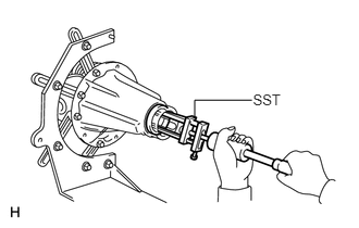
Using SST, tap out the front drive pinion rear tapered roller bearing (outer race).
- SST
-
09308-00010
If the front drive pinion rear tapered roller bearing is damaged during removal, replace it.
41211A 22.REMOVE FRONT DRIVE PINION FRONT TAPERED ROLLER BEARING
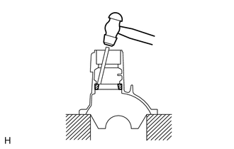
Using a brass bar and hammer, tap out the front drive pinion front tapered roller bearing (outer race).
If the front drive pinion front tapered roller bearing is damaged during removal, replace it.
41115F 23.REMOVE FRONT DIFFERENTIAL OIL STORAGE RING
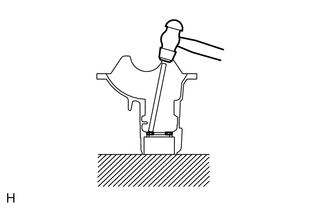
Using a hammer and brass bar, tap out the front differential oil storage ring.
24.REMOVE DIFFERENTIAL RING GEAR
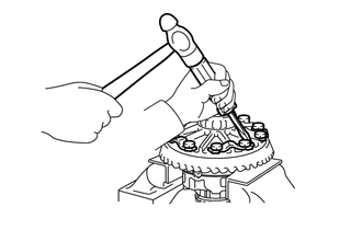
Using a screwdriver, unstake the lock plate.
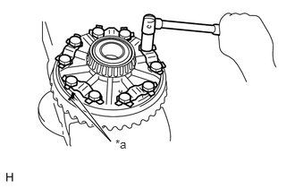
| *a | Matchmark |
Place matchmarks on the differential ring gear and front differential case.
Remove the 10 bolts and 5 lock plates.
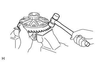
Using a plastic-faced hammer, tap on the differential ring gear to separate it from the front differential case.
41311 25.INSPECT RUNOUT OF FRONT DIFFERENTIAL CASE
- HINT:
-
If the differential ring gear runout is at the maximum or less, this inspection is not necessary.
Install the 2 front differential case bearings (outer race) to the front differential case.
Install the front differential case to the differential carrier.
Install the 2 front differential bearing adjusting nuts.
Install the 2 bearing caps to the differential carrier with the 4 bolts.
- Torque:
- 85.3 N*m (870 kgf*cm, 63 ft.*lbf)
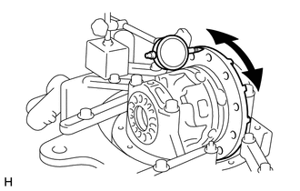
Inspect the front differential case runout.
- Maximum runout:
-
0.04 mm (0.00157 in.)
Remove the 4 bolts and 2 bearing caps.
Remove the 2 front differential bearing adjusting nuts.
Remove the front differential case.
Remove the 2 front differential case bearings (outer race).
41311A 26.REMOVE FRONT DIFFERENTIAL CASE BEARING
- HINT:
-
The differential case and case bearings should only be removed when replacement is necessary.
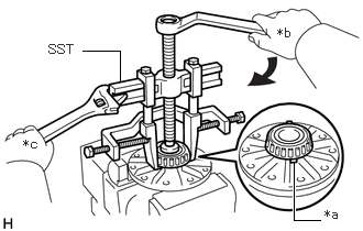
| *a | Notch |
| *b | Turn |
| *c | Hold |
Using SST, remove the 2 front differential case bearings (inner race) from the front differential case.
- SST
-
09950-60010 (09951-00480)
09950-40011 (09951-04020, 09952-04010, 09953-04030, 09954-04010, 09955-04061, 09958-04011)
- HINT:
-
Attach the claws of SST to the notch in the front differential case to secure SST.
27. DISASSEMBLE FRONT DIFFERENTIAL CASE
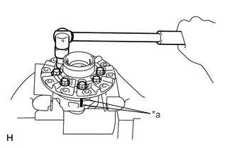
| *a | Matchmark |
Place matchmarks on the front differential case LH and RH.
Remove the 8 bolts uniformly, a little at a time.
Using a plastic-faced hammer, separate the front differential case LH and RH.
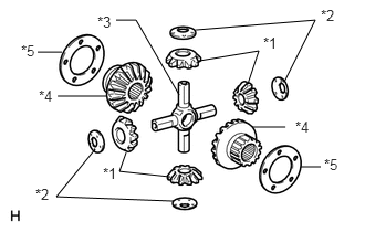
| *1 | Front Differential Pinion |
| *2 | Front Differential Pinion Thrust Washer |
| *3 | Front Differential Spider |
| *4 | Front Differential Side Gear |
| *5 | Front No. 1 Differential Side Gear Thrust Washer |
Remove the 4 front differential pinions, 4 front differential pinion thrust washers, 2 front differential side gears, 2 front No. 1 differential side gear thrust washers and front differential spider from the front differential case.
41453A 28.INSPECT FRONT DIFFERENTIAL LOCK SLEEVE
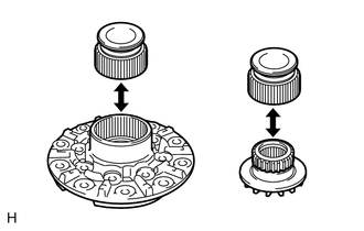
Install the front differential lock sleeve to the front differential case LH and check that it moves smoothly.
Install the front differential lock sleeve to the front differential side gear and check that it moves smoothly.
29.INSPECT SHIFT FORK AND SLEEVE
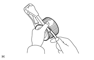
Using a feeler gauge, measure the clearance between the front differential lock shift fork and front differential lock sleeve.
- Standard clearance (reference):
-
0.15 to 0.35 mm (0.0060 to 0.0137 in.)