HEATING / AIR CONDITIONING CONDENSER(for 1HZ LHD) INSTALLATION
PROCEDURE

 88460 1.INSTALL COOLER CONDENSER ASSEMBLY
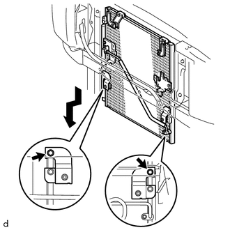
Install the cooler condenser assembly with the 2 bolts as shown in the illustration.
- Torque:
- 5.0 N*m (51 kgf*cm, 44 in.*lbf)
88716B 2.CONNECT COOLER REFRIGERANT LIQUID PIPE B
Remove the attached vinyl tape from the pipe and the connecting part of the cooler condenser assembly.
Sufficiently apply compressor oil to a new O-ring and the fitting surface of the pipe joint.
- Compressor oil:
-
ND-OIL 8 or equivalent
Install the O-ring on the cooler refrigerant liquid pipe B.
Connect the cooler refrigerant liquid pipe B on the cooler condenser assembly with the nut.
- Torque:
- 5.0 N*m (51 kgf*cm, 44 in.*lbf)
- NOTICE:
-
·
When tightening the nut, do not allow any tools to contact the pipe.
·When tightening the nut, hold a part of the pipe near the connector.
88711 3.CONNECT NO. 1 COOLER REFRIGERANT DISCHARGE HOSE
Remove the attached vinyl tape from the hose and the connecting part of the cooler condenser assembly.
Sufficiently apply compressor oil to a new O-ring and the fitting surface of the hose joint.
- Compressor oil:
-
ND-OIL 8 or equivalent
Install the O-ring on the No. 1 cooler refrigerant discharge hose.
Connect the No. 1 cooler refrigerant discharge hose on the cooler condenser assembly with the bolt.
- Torque:
- 5.0 N*m (51 kgf*cm, 44 in.*lbf)
- NOTICE:
-
·
When tightening the bolt, do not allow any tools to contact the pipe.
·When tightening the bolt, hold a part of the pipe near the connector.
53205 4.INSTALL UPPER RADIATOR SUPPORT SUB-ASSEMBLY
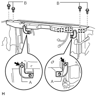
Install the upper radiator support sub-assembly with the 6 bolts.
- Torque:
- for bolt A : 5.0 N*m (51 kgf*cm, 44 in.*lbf)
- for bolt B : 13 N*m (133 kgf*cm, 10 ft.*lbf)
Attach the 3 clamps.
53510 5.INSTALL HOOD LOCK ASSEMBLY
Install the hood lock assembly with the 2 bolts.
- Torque:
- 7.8 N*m (80 kgf*cm, 69 in.*lbf)
53217A 6.INSTALL HOOD LOCK SUPPORT BRACE
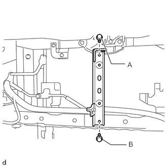
Install the hood lock support brace with the 2 bolts.
- Torque:
- for Bolt A : 7.8 N*m (80 kgf*cm, 69 in.*lbf)
- for Bolt B : 13 N*m (133 kgf*cm, 10 ft.*lbf)
86510 7.INSTALL HIGH PITCHED HORN ASSEMBLY
Click hereVehicle Exterior>HORN>HORN>INSTALLATION
86520 8.INSTALL LOW PITCHED HORN ASSEMBLY
Click hereVehicle Exterior>HORN>HORN>INSTALLATION
16400 9.INSTALL RADIATOR ASSEMBLY
52119A 10.INSTALL FRONT BUMPER COVER
for Standard:
Click hereVehicle Exterior>EXTERIOR PANELS / TRIM>FRONT BUMPER (for Standard)>INSTALLATION
for Step Type:
Click hereVehicle Exterior>EXTERIOR PANELS / TRIM>FRONT BUMPER (for Step Type)>INSTALLATION
53111 11.INSTALL RADIATOR GRILLE
12.CHARGE AIR CONDITIONING SYSTEM WITH REFRIGERANT
13.WARM UP ENGINE
14.CHECK FOR REFRIGERANT GAS LEAK