FRONT SUSPENSION FRONT STABILIZER BAR INSTALLATION
PROCEDURE

 1.INSTALL BUSHING
Install 2 new bushings and the 2 collars to the front stabilizer bar.
48829A 2.INSTALL FRONT NO. 1 STABILIZER BRACKET LH
except 1GR-FE:
Install the front No. 1 stabilizer bracket to the chassis frame with the 4 bolts.
- Torque:
- 25 N*m (255 kgf*cm, 18 ft.*lbf)
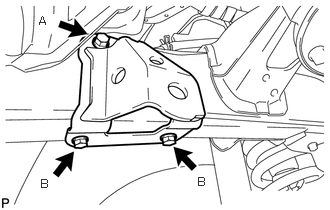
for 1GR-FE:
Install the stabilizer bracket to the chassis frame with the 3 bolts.
- Torque:
- Bolt A : 53 N*m (540 kgf*cm, 39 ft.*lbf)
- Bolt B : 25 N*m (255 kgf*cm, 18 ft.*lbf)
- NOTICE:
-
Tighten the bolt A first.
48824A 3.INSTALL FRONT NO. 1 STABILIZER BRACKET RH
- HINT:
-
Use the same procedure described for the LH side.
48815 4.INSTALL FRONT NO. 1 STABILIZER BAR BUSHING
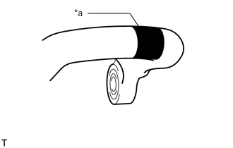
| *a | Paint Line |
except 1GR-FE:
Install the front No. 1 stabilizer bar bushing over the paint line on the front stabilizer bar.
Install the 2 front No. 1 stabilizer bar bushings to the front stabilizer bar.
for 1GR-FE:
Install the 2 front No. 1 stabilizer bar bushings to the front stabilizer bar.
48802F 5.TEMPORARILY INSTALL FRONT STABILIZER LINK SUB-ASSEMBLY LH
Temporarily install the front stabilizer link sub-assembly to the front No. 1 stabilizer bracket with the nut and washer.
48802F 6.TEMPORARILY INSTALL FRONT STABILIZER LINK SUB-ASSEMBLY RH
- HINT:
-
Use the same procedure described for the LH side.
48811 7.TEMPORARILY INSTALL FRONT STABILIZER BAR
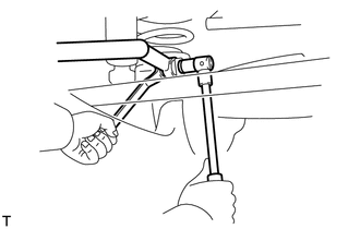
Temporarily install the front stabilizer bar to the front axle housing assembly with the bolt and a new nut.
- HINT:
-
Use the same procedure described for the other side.
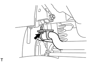
Temporarily install the front stabilizer bar to the front stabilizer links with the 4 bolts.
8.INSTALL FRONT WHEEL
9.STABILIZE SUSPENSION
48802F 10.TIGHTEN FRONT STABILIZER LINK SUB-ASSEMBLY LH
Tighten the front stabilizer link sub-assembly to the front No. 1 stabilizer bracket with the nut.
- Torque:
- 117 N*m (1193 kgf*cm, 86 ft.*lbf)
48802F 11.TIGHTEN FRONT STABILIZER LINK SUB-ASSEMBLY RH
- HINT:
-
Use the same procedure described for the LH side.
48811 12.TIGHTEN FRONT STABILIZER BAR
Tighten the front stabilizer bar to the front axle housing assembly with the bolt and a new nut.
- Torque:
- 52 N*m (530 kgf*cm, 38 ft.*lbf)
- HINT:
-
Use the same procedure described for the other side.
Tighten the front stabilizer bar to the front stabilizer links with the 4 bolts.
- Torque:
- 29.7 N*m (303 kgf*cm, 22 ft.*lbf)
48520 13.CONNECT FRONT SHOCK ABSORBER ASSEMBLY LH (for 1GR-FE)
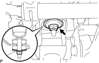
Install the front No. 2 shock absorber cushion retainer and front shock absorber assembly LH with a new nut.
- HINT:
-
Install the front No. 2 shock absorber cushion retainer in the direction shown in the illustration.
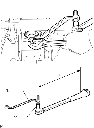
| *a | Torque Wrench Fulcrum Length |
| *b | Long Offset Wrench |
| *c | Hexagon Wrench |
Secure the width across flats of the front shock absorber assembly LH and using a 14 mm hexagon wrench and 14 mm x 17 mm long offset wrench, install the front shock absorber assembly LH with a new nut.
- Torque:
- Specified tightening torque : 68.6 N*m (700 kgf*cm, 51 ft.*lbf)
- HINT:
-
·
Calculate the torque wrench reading when changing the fulcrum length of the torque wrench.
Click hereGeneral>INTRODUCTION>REPAIR INSTRUCTION>PRECAUTION
48510 14.CONNECT FRONT SHOCK ABSORBER ASSEMBLY RH (for 1GR-FE)
- HINT:
-
Use the same procedure described for the LH side.
15.INSTALL WIRE HARNESS CLAMP (w/ Differential Lock)
Install the bolt and connect the wire harness clamp assembly.
- Torque:
- 5.4 N*m (55 kgf*cm, 48 in.*lbf)