STEERING GEAR / LINKAGE STEERING GEAR REASSEMBLY
CAUTION / NOTICE / HINT
- NOTICE:
-
·
When using a vise, place aluminum plates between the part and vise.
·When using a vise, do not overtighten it.
- HINT:
-
·
Use the same procedure for RHD and LHD vehicles.
·The procedure listed below is for LHD vehicles.
PROCEDURE

 45357 1.INSTALL SECTOR SHAFT ADJUSTING SCREW
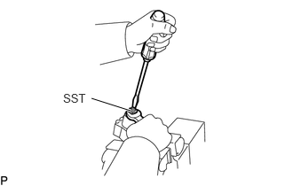
Using SST, install a new sector shaft adjusting screw to the cross shaft.
- SST
-
09630-00014 (09631-00051)
- HINT:
-
Adjust the sector adjusting screw for correct thrust clearance.
-
Click hereSteering>STEERING GEAR / LINKAGE>STEERING GEAR>INSPECTION
Stake the lock nut.
44105C 2.INSTALL VALVE BODY HOUSING UNION SEAT
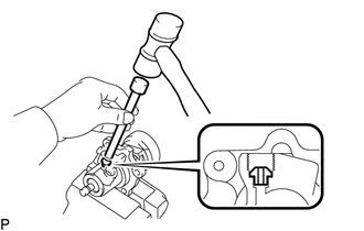
Using a plastic-faced hammer and extension bar, tap in 2 new valve body housing union seats.
- NOTICE:
-
Do not allow any shards into the port.
44114A 3.INSTALL POWER PISTON NUT RING ("TEFLON" RING)
Apply power steering fluid to a new O-ring.
Install the O-ring to the power piston nut.
Expand a new power piston nut ring ("Teflon" Ring) with your fingers.
- NOTICE:
-
Be careful not to over-expand the power piston nut ring ("Teflon" Ring).
Install the power piston nut ring ("Teflon" Ring) to the power piston nut.
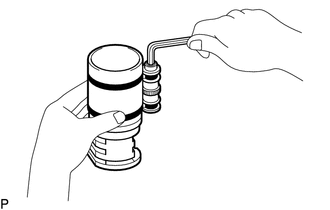
Coat the power piston nut ring ("Teflon" Ring) with power steering fluid and snug it down with piston ring compressor for 5 to 7 minutes.
44107A 4.INSTALL POWER STEERING GEAR HOUSING NEEDLE ROLLER BEARING
Apply MP grease to a new power steering gear housing needle roller bearing (lower).
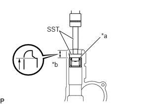
| *a | Bearing supplier mark side |
| *b | 23.1 mm (0.909 in.) |
Using SST, press in the power steering gear housing needle roller bearing (lower).
- SST
-
09950-60010 (09951-00350, 09951-00420, 09952-06010)
09950-70010 (09951-07100)
- HINT:
-
Install the power steering gear housing needle roller bearing (lower) so that it is positioned 23.1 mm (0.909 in.) away from the housing inner end surface.
Apply MP grease to the power steering gear housing needle roller bearing (upper).
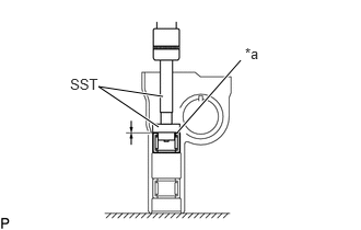
| *a | Bearing supplier mark side |
Using SST, press in the power steering gear housing needle roller bearing (upper).
- SST
-
09950-60010 (09951-00350, 09951-00420, 09952-06010)
09950-70010 (09951-07100)
- HINT:
-
The power steering gear housing needle roller bearings (upper) top end should be installed so that it aligns with the housing end surface.
Apply power steering fluid to the O-ring.
Install the O-ring and power steering gear housing ring to the power steering gear housing.
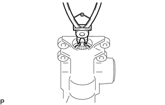
Using a snap ring pliers, install the power steering gear housing hole snap ring.
Apply power steering fluid to a new power steering gear housing ring ("Teflon" Ring).
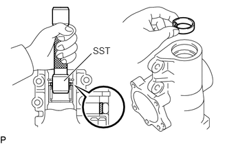
Form the new power steering gear housing ring ("Teflon" Ring) in to a heater shape and install it with hand.
Using SST, from the power steering gear housing ring ("Teflon" Ring).
- SST
-
09630-00014 (09631-00121)
- NOTICE:
-
The power steering gear housing ring ("Teflon" Ring) must be squeezed before inserting the sector shaft or damage will result.
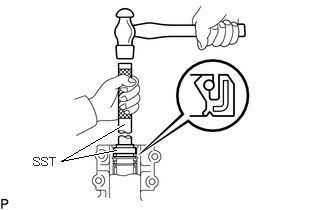
Using SST, tap in a new power steering housing oil seal into the power steering gear housing.
- SST
-
09950-70010 (09951-07100)
09630-00014 (09631-00091)
- HINT:
-
Coat the lip of a new oil seal with MP grease.
44120 5.INSTALL WITH BALL NUT VALVE ASSEMBLY
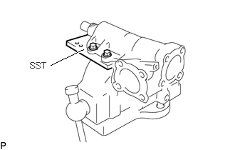
Mount the power steering gear housing on SST and clamp SST in vise.
- SST
-
09630-00014 (09631-00142)
Apply power steering fluid to the new 2 power steering gear housing ring ("Teflon" Ring).
Install the 2 O-rings to the power steering gear housing.
Install a new O-ring to the valve housing of the valve assembly (with ball nut).
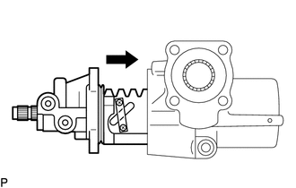
Insert the valve assembly (with ball nut) to the power steering gear housing as shown.
- NOTICE:
-
Do not damage the power piston nut ring ("Teflon" Ring).
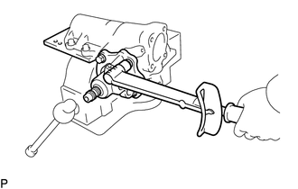
Install the 4 bolts.
- Torque:
- 61 N*m (622 kgf*cm, 45 ft.*lbf)
Using SST, check the valve assembly (with ball nut) preload.
Click hereSteering>STEERING GEAR / LINKAGE>STEERING GEAR>INSPECTION
44154 6.INSTALL POWER PISTON PLUNGER GUIDE NUT
Apply power steering fluid to a new O-ring.
Install the O-ring to the plunger guide nut.
Install the power piston plunger, power piston plunger guide and power piston plunger spring.
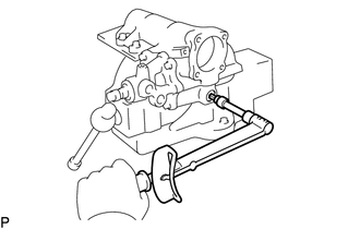
Install the plunger guide nut with hexagon wrench.
- Torque:
- 20 N*m (204 kgf*cm, 15 ft.*lbf)
Stake the plunger guide nut.
44111 7.INSTALL CROSS SHAFT
Apply power steering fluid to a new O-ring.
Install the O-ring on the side cover sub-assembly.
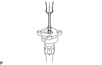
Using a screwdriver, assemble the cross shaft to the side cover sub-assembly.
- HINT:
-
Fully loosen the sector shaft adjusting screw.
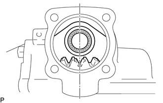
Set the worm gear at the center of the power steering gear housing.
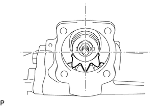
Insert and push the cross shaft into the power steering gear housing so that the center teeth mesh together.
- NOTICE:
-
Do not damage the oil seal.
44108 8.INSTALL SIDE COVER SUB-ASSEMBLY
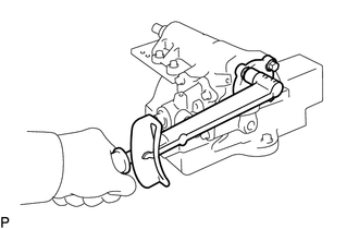
Install the 4 bolts, Tighten the bolts in a diagonal pattern.
- Torque:
- 61 N*m (622 kgf*cm, 45 ft.*lbf)
9.ADJUST TOTAL PRELOAD
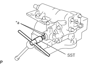
| *a | Matchmark |
Using SST, turn the worm shaft so full lock in both directions and determine the exact center.
- SST
-
09616-00011
Place matchmarks on the worm shaft and housing to show neutral position.
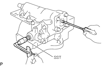
Install SST with a torque meter on the worm shaft.
- SST
-
09616-00011
Turn the adjusting screw while measuring the preload until it is correct.
- Total Preload:
-
0.735 to 1.08 N*m (8 to 11 kgf*cm, 7 to 9 in.*lbf)
Install a new cross shaft adjusting screw seal washer.
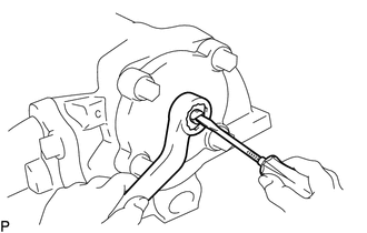
Install the nut while holding the adjusting screw.
- Torque:
- 46 N*m (469 kgf*cm, 34 ft.*lbf)
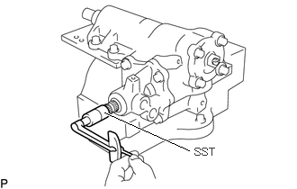
Check the total preload.
- SST
-
09616-00011
- Total Preload:
-
0.735 to 1.08 N*m (8 to 11 kgf*cm, 7 to 9 in.*lbf)