DRIVE SHAFT / PROPELLER SHAFT PROPELLER SHAFT ASSEMBLY REASSEMBLY
CAUTION / NOTICE / HINT
- NOTICE:
-
·
When using a vise, place aluminum plates between the part and vise.
·When using a vise, do not overtighten it.
PROCEDURE

 1.INSTALL SPIDER BEARING
- HINT:
-
Use the same procedure for both spiders.
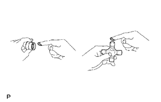
Apply MP grease to a new spider and new spider bearing.
- NOTICE:
-
Do not apply too much grease.
Install the grease fitting to the spider.
- Torque:
- 6.3 N*m (64 kgf*cm, 56 in.*lbf)
Install the spider to the propeller shaft.
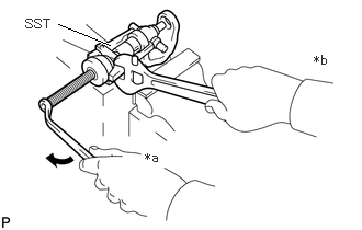
| *a | Turn |
| *b | Hold |
Using SST, install 2 of the spider bearings to the spider.
- SST
-
09332-25010
Using SST, adjust both spider bearing so that the rear propeller shaft joint spider bearing snap ring grooves are at maximum and in equal in width.
- SST
-
09332-25010
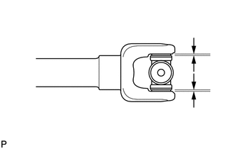
Install 4 new rear propeller shaft joint spider bearing snap rings of equal thickness which will allow no axial play.
- HINT:
-
Do not reuse the rear propeller shaft joint spider bearing snap rings.
| Color | Mark | Thickness |
|---|---|---|
| - | 1 | 1.980 to 2.000 mm (0.0780 to 0.0787 in.) |
| - | - | 1.985 to 2.015 mm (0.0782 to 0.0793 in.) |
| - | 2 | 2.000 to 2.020 mm (0.0788 to 0.0795 in.) |
| Brown | - | 2.015 to 2.045 mm (0.0794 to 0.0805 in.) |
| - | 3 | 2.020 to 2.040 mm (0.0796 to 0.0803 in.) |
| - | 4 | 2.040 to 2.060 mm (0.0804 to 0.0811 in.) |
| Blue | - | 2.045 to 2.075 mm (0.0806 to 0.0816 in.) |
| - | 5 | 2.060 to 2.080 mm (0.0812 to 0.0818 in.) |
| - | - | 2.075 to 2.105 mm (0.0817 to 0.0828 in.) |
| - | 6 | 2.080 to 2.100 mm (0.0819 to 0.0826 in.) |
| - | 7 | 2.100 to 2.120 mm (0.0827 to 0.0834 in.) |
| - | 8 | 2.120 to 2.140 mm (0.0835 to 0.0842 in.) |
| - |

|
2.140 to 2.160 mm (0.0843 to 0.0850 in.) |
| - | 10 | 2.160 to 2.180 mm (0.0851 to 0.0858 in.) |
- NOTICE:
-
·
Use a new rear propeller shaft joint spider bearing snap ring.
·Use rear propeller shaft joint spider bearing snap rings with as close to the same thickness as possible on both ends.
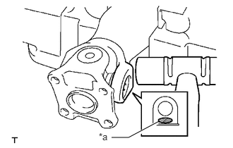
| *a | Hammering Point |
Using a plastic-faced hammer, tap the flange yoke until there is no clearance between the spider bearing outer race and rear propeller shaft joint spider bearing snap rings.
- HINT:
-
Install the spider bearing on the sleeve side using the procedure described above.
2.INSPECT PROPELLER SHAFT GREASE FITTING DIRECTION
- HINT:
-
·
When replacing a spider bearing, be sure that the grease fitting hole is facing the direction shown in the illustration.
·Fill the grease fittings with MP grease.
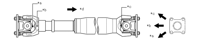
| *a | No. 1 Grease Fitting | *b | No. 2 Grease Fitting |
| *c | No. 3 Grease Fitting | *d | Rear Side |
3.INSPECT SPIDER BEARING