METER / GAUGE / DISPLAY METER / GAUGE SYSTEM Oil Pressure Gauge Malfunction
DESCRIPTION
The combination meter receives an oil pressure signal from the oil pressure sender gauge assembly. The oil pressure gauge needle position changes based on the resistance of the oil pressure sender gauge assembly.
WIRING DIAGRAM
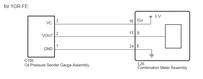
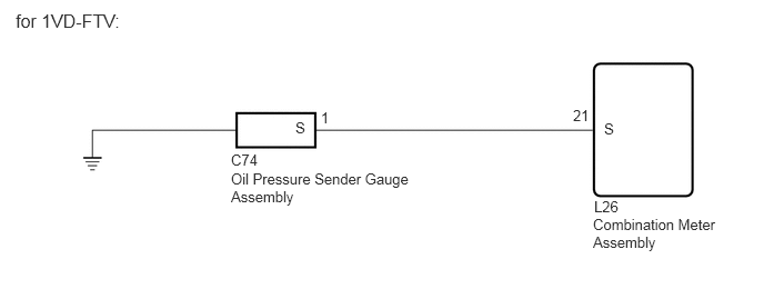
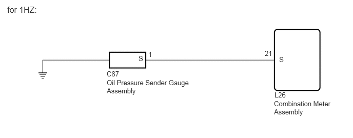
PROCEDURE
Check vehicle type.
- Result:
-
Result Proceed to for 1GR-FE A for 1VD-FTV, 1HZ B
A
B
Disconnect the L26 combination meter assembly connector.
Disconnect the C105 oil pressure sender gauge assembly connector.
Measure the resistance according to the value(s) in the table below.
- Standard Resistance:
-
Tester Connection Condition Specified Condition L26-16 (IG+) - C105-3 (VC) Always Below 1 Ω L26-17 (S) - C105-2 (VOUT) Always Below 1 Ω L26-24 (E) - C105-1 (GND) Always Below 1 Ω L26-16 (IG+) or C105-3 (VC) - Body ground Always 10 kΩ or higher L26-17 (S) or C105-2 (VOUT) - Body ground Always 10 kΩ or higher L26-24 (E) or C105-1 (GND) - Body ground Always 10 kΩ or higher
- Result:
-
Proceed to OK NG
OK
NG
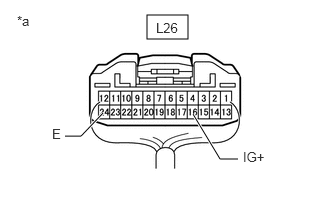
| *a | Component with harness connected (Combination Meter Assembly) |
Remove the combination meter assembly with the connector(s) still connected.
Click hereVehicle Interior>METER / GAUGE / DISPLAY>COMBINATION METER>REMOVAL
Measure the resistance according to the value(s) in the table below.
- Standard Resistance:
-
Tester Connection Condition Specified Condition L26-24 (E) - Body ground Always Below 1 Ω
Measure the voltage according to the value(s) in the table below.
- Standard Voltage:
-
Tester Connection Switch Condition Specified Condition L26-16 (IG+) - Body ground Ignition switch ON 4.75 to 5.25 V Ignition switch off Below 1 V
- Result:
-
Proceed to OK NG
OK
NG
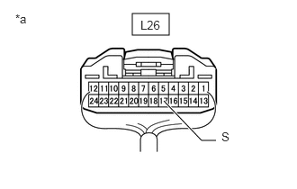
| *a | Component with harness connected (Combination Meter Assembly) |
Remove the combination meter assembly with the connector(s) still connected.
Click hereVehicle Interior>METER / GAUGE / DISPLAY>COMBINATION METER>REMOVAL
Measure the voltage according to the value(s) in the table below.
- Standard Voltage:
-
Tester Connection Switch Condition Specified Condition L26-17 (S) - Body ground Ignition switch ON 0 to 5 V
- Result:
-
Proceed to OK NG
OK
NG
Remove the oil pressure sender gauge assembly.
for 1VD-FTV:
Click hereEngine / Hybrid System>1VD-FTV (LUBRICATION)>OIL PRESSURE SENSOR>REMOVAL
for 1HZ:
Click hereEngine / Hybrid System>1HZ (LUBRICATION)>OIL PRESSURE SENSOR>REMOVAL
Inspect the oil pressure sender gauge assembly.
for 1VD-FTV:
Click hereEngine / Hybrid System>1VD-FTV (LUBRICATION)>OIL PRESSURE SENSOR>INSPECTION
for 1HZ:
Click hereEngine / Hybrid System>1HZ (LUBRICATION)>OIL PRESSURE SENSOR>ON-VEHICLE INSPECTION
- Result:
-
Proceed to OK NG
OK
NG
for 1VD-FTV:
Click hereEngine / Hybrid System>1VD-FTV (LUBRICATION)>OIL PRESSURE SENSOR>REMOVAL
for 1HZ:
Click hereEngine / Hybrid System>1HZ (LUBRICATION)>OIL PRESSURE SENSOR>REMOVAL
Disconnect the L26 combination meter assembly connector.
Disconnect the C74*1 or C87*2 oil pressure sender gauge assembly connector.
*1: for 1VD-FTV
*2: for 1HZ
Measure the resistance according to the value(s) in the table below.
- Standard Resistance:
-
for 1VD-FTV Tester Connection Condition Specified Condition L26-21 (S) - C74-1 (S) Always Below 1 Ω L26-21 (S) or C74-1 (S) - Body ground Always 10 kΩ or higher
-
for 1HZ Tester Connection Condition Specified Condition L26-21 (S) - C87-1 (S) Always Below 1 Ω L26-21 (S) or C87-1 (S) - Body ground Always 10 kΩ or higher
- Result:
-
Proceed to OK NG
OK
NG