1GR-FE INTAKE / EXHAUST INTAKE MANIFOLD INSTALLATION
PROCEDURE

 17111 1.INSTALL INTAKE MANIFOLD
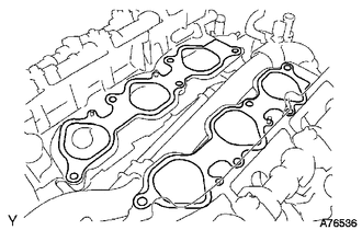
Set a new gasket on each cylinder head sub-assembly.
- NOTICE:
-
·
Align the port holes of the gasket and cylinder head sub-assembly.
-
·
Make sure the gaskets are installed facing the proper direction.
Set the intake manifold on the cylinder head sub-assemblies.
Install and uniformly tighten the 10 bolts in several passes.
- Torque:
- 26 N*m (265 kgf*cm, 19 ft.*lbf)
- HINT:
-
Tighten the inner installation bolts of the intake manifold before tightening the outer bolts.
23807 2.INSTALL FUEL DELIVERY PIPE SUB-ASSEMBLY
23802B 3.INSTALL NO. 2 FUEL PIPE SUB-ASSEMBLY
23801P 4.INSTALL NO. 1 FUEL PIPE SUB-ASSEMBLY
17129 5.INSTALL INTAKE AIR SURGE TANK
- NOTICE:
- Do not apply oil to the bolts and nuts listed below: :
-
Oil Application Prohibited Bolt/Nut Bolt for surge tank and intake manifold Nut for surge tank and intake manifold
Install a new gasket to the intake air surge tank.
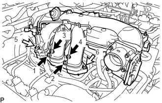

|
Bolt |

|
Nut |
Using an 8 mm hexagon wrench, install the intake air surge tank with the 4 bolts and 2 nuts in the order shown in the illustration.
- Torque:
- 28 N*m (286 kgf*cm, 21 ft.*lbf)
Install the No. 2 surge tank stay with the 2 bolts.
- Torque:
- 21 N*m (214 kgf*cm, 15 ft.*lbf)
Connect the clutch hose bracket with the 2 nuts.
- Torque:
- 20 N*m (204 kgf*cm, 15 ft.*lbf)
Attach the wire harness clamp.
Install the No. 1 surge tank stay with the 2 bolts.
- Torque:
- 21 N*m (214 kgf*cm, 15 ft.*lbf)
Install the oil baffle plate with the bolt.
- Torque:
- 9.0 N*m (92 kgf*cm, 80 in.*lbf)
Connect the engine oil level dipstick guide to the No. 1 surge tank stay with the bolt.
- Torque:
- 9.0 N*m (92 kgf*cm, 80 in.*lbf)
Connect the ground wire to the No. 1 surge tank stay with the bolt.
- Torque:
- 8.4 N*m (86 kgf*cm, 74 in.*lbf)
Attach the wire harness clamp to the No. 1 surge tank stay.
Install the throttle body bracket with the 2 bolts.
- Torque:
- 21 N*m (214 kgf*cm, 15 ft.*lbf)
Connect the vacuum switching valve (for ACIS) connector.
Connect the No. 1 ventilation hose to the intake air surge tank, and slide the clamp to secure the hose.
Connect the No. 1 vacuum switching valve connector.
Connect the No. 1 fuel vapor feed hose to the No. 1 vacuum switching valve assembly, and slide the clamp to secure the hose.
Connect the No. 5 water by-pass hose to the water inlet housing, and slide the clamp to secure the hose.
Connect the No. 4 water by-pass hose to the water inlet housing, and slide the clamp to secure the hose.
Connect the throttle body connector.
17705 6.INSTALL AIR CLEANER CAP SUB-ASSEMBLY WITH NO. 1 AIR CLEANER HOSE
Attach the 3 clamps and install the air cleaner cap sub-assembly with No. 1 air cleaner hose.
Connect the No. 1 air cleaner hose to the cylinder head cover sub-assembly with the bolt.
- Torque:
- 5.0 N*m (51 kgf*cm, 44 in.*lbf)
Tighten the hose clamp.
- Torque:
- 2.5 N*m (25 kgf*cm, 22 in.*lbf)
Attach the clamp and connect the wire harness.
Connect the No. 2 ventilation hose to the No. 1 air cleaner hose, and slide the clamp to secure the hose.
Connect the vacuum hose to the No. 1 air cleaner hose.
Attach the clamp and connect the mass air flow meter connector.
7.CONNECT CABLE TO NEGATIVE BATTERY TERMINAL
8. INITIALIZATION AFTER RECONNECTING BATTERY TERMINAL
- HINT:
-
When disconnecting and reconnecting the battery, there is an automatic learning function that completes learning when the respective system is used.
-
Click hereGeneral>SETUP>WHEN DISCONNECTING OR RECONNECTING BATTERY TERMINAL>AUTOMATIC LEARNING CHART
9.ADD ENGINE COOLANT
10.INSPECT FOR COOLANT LEAK
11.INSPECT FOR FUEL LEAK