RM37H0E
_52
Drivetrain
_093826
Q710 HYBRID TRANSMISSION / TRANSAXLE
_0442247
SHIFT LEVER KNOB
A
Q710 HYBRID TRANSMISSION / TRANSAXLE SHIFT LEVER KNOB INSTALLATION
CAUTION / NOTICE / HINT
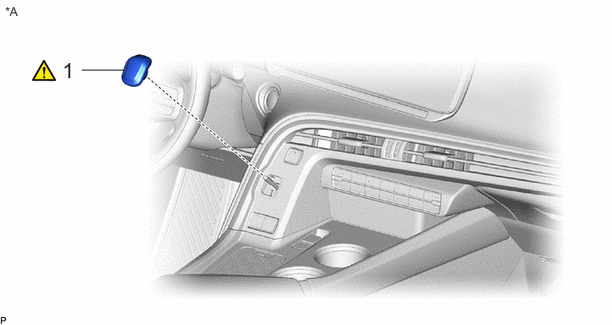
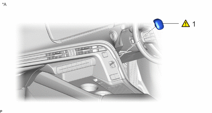
COMPONENTS (INSTALLATION)
0.958,0.823 1.458,0.823
false
0.063,0.052 0.313,0.281
0.25,0.229
10
false
*A
0.729,0.677 0.969,1.042
0.24,0.365
18
false
1
| Procedure | Part Name Code | 
|

|

|
|
|---|---|---|---|---|---|
| 1 | SHIFT LEVER KNOB SUB-ASSEMBLY | 33504F | ( ) |
- | - |
| *A | for LHD | - | - |
5.5,0.792 6.042,0.792
false
6.49,0.656 6.771,1.01
0.281,0.354
18
false
1
0.073,0.063 0.344,0.302
0.271,0.24
10
false
*A
| Procedure | Part Name Code |
|
|
|
|
|---|---|---|---|---|---|
| 1 | SHIFT LEVER KNOB SUB-ASSEMBLY | 33504F | ()
|
- | - |
| *A | for RHD | - | - |
PROCEDURE

 33504F
1.INSTALL SHIFT LEVER KNOB SUB-ASSEMBLY
a.
5.531,2.875 5.99,2.5
5.99,2.5 6.25,2.5
true
1.615,2.875 1.198,2.5
1.198,2.5 0.885,2.5
true
4.563,3.427 4.875,3.427
4.875,3.427 5.271,3.115
true
2.677,3.49 2.344,3.49
2.344,3.49 1.896,3.125
true
0.5,0.458 0.74,0.677
0.24,0.219
10
true
*A
3.927,0.458 4.188,0.667
0.26,0.208
10
true
*B
0.396,0.073 1.042,0.417
0.646,0.344
18
false
i - iii
2.719,3.385 3,3.656
0.281,0.271
10
false
*a
4.354,3.313 4.615,3.552
0.26,0.24
10
false
*a
0.688,2.406 0.906,2.698
0.219,0.292
10
false
*b
6.281,2.417 6.542,2.667
0.26,0.25
10
false
*b
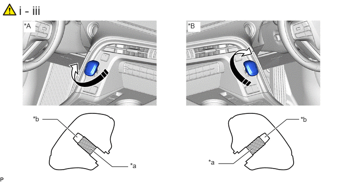
| *A | for LHD | *B | for RHD |
| *a | Threaded Portion | *b | Non-threaded Portion |

|
Turn the shift lever knob sub-assembly in the direction indicated by the arrow shown in the illustration | - | - |
i.
Turn the shift lever knob sub-assembly in the direction indicated by the arrow shown in the illustration until rotation becomes difficult.
- NOTICE:
-
When rotation becomes difficult, the shift lock control unit assembly (shaft) has reached the non-threaded portion on the inside of the shift lever knob sub-assembly.
- HINT:
- Specified tightening torque
-
5.0 to 8.0 N*m (51 to 81 kgf*cm, 45 to 70 in.*lbf)
ii.
From this point, tighten by another turn in the direction indicated by the arrow shown in the illustration.
iii.
In addition, align shift lever knob sub-assembly to the front and rear direction of the vehicle.