NAVIGATION / MULTI INFO DISPLAY MULTI-DISPLAY ECU INSTALLATION
CAUTION / NOTICE / HINT
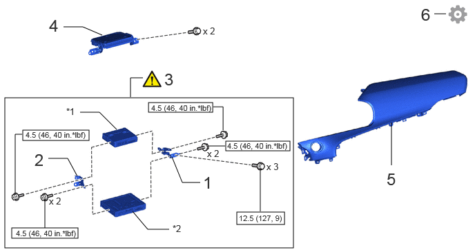
| Procedure | Part Name Code | 
|

|

|
|
|---|---|---|---|---|---|
| 1 | NO. 2 INTEGRATION CONTROL BRACKET | 84113J | - | - | - |
| 2 | NO. 1 INTEGRATION CONTROL BRACKET | 84113H | - | - | - |
| 3 | TELEMATICS TRANSCEIVER WITH BRACKET | - | ( ) |
- | - |
| 4 | NAVIGATION ECU ASSEMBLY WITH BRACKET | - | - | - | - |
| 5 | NO. 2 INSTRUMENT PANEL SAFETY PAD SUB-ASSEMBLY | 55403E | - | - | - |
| 6 | INITIALIZATION AFTER RECONNECTING AUXILIARY BATTERY TERMINAL | - | - | - | ()
|
| *1 | TELEMATICS TRANSCEIVER | *2 | INTEGRATION CONTROL SUB-ASSEMBLY |

|
N*m (kgf*cm, ft.*lbf): Specified torque | - | - |
- HINT:
- ·
Use the same procedure for RHD and LHD vehicles.
·The procedure listed below is for LHD vehicles.
PROCEDURE

 84113J
1.INSTALL NO. 2 INTEGRATION CONTROL BRACKET
- Torque:
- 4.5 N*m (46 kgf*cm, 40 in.*lbf)
84113H
2.INSTALL NO. 1 INTEGRATION CONTROL BRACKET
- Torque:
- 4.5 N*m (46 kgf*cm, 40 in.*lbf)
3.INSTALL TELEMATICS TRANSCEIVER WITH BRACKET
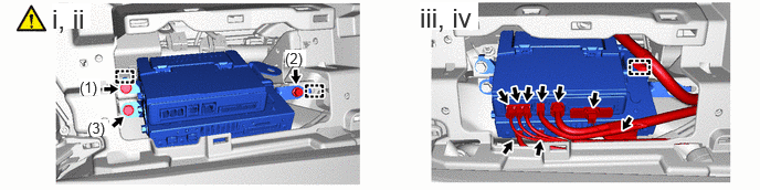
Attach the guide to temporarily install the telematics transceiver with bracket.
Install the telematics transceiver with bracket with the 3 bolts in the order shown in the illustration.
- Torque:
- 12.5 N*m (127 kgf*cm, 9 ft.*lbf)
Attach the clamp.
Connect each connector.
4.INSTALL NAVIGATION ECU ASSEMBLY WITH BRACKET
55403E
5.INSTALL NO. 2 INSTRUMENT PANEL SAFETY PAD SUB-ASSEMBLY
6. INITIALIZATION AFTER RECONNECTING AUXILIARY BATTERY TERMINAL
Click hereGeneral>SETUP>WHEN DISCONNECTING OR RECONNECTING BATTERY TERMINAL>WORK PROCEDURE
- HINT:
-
When disconnecting and reconnecting the auxiliary battery, there is an automatic learning function that completes learning when the respective system is used.
-
Click hereGeneral>SETUP>WHEN DISCONNECTING OR RECONNECTING BATTERY TERMINAL>AUTOMATIC LEARNING CHART