MIRROR (EXT) OUTER REAR VIEW MIRROR GLASS REMOVAL
CAUTION / NOTICE / HINT
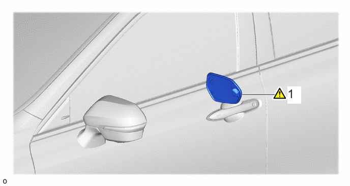
| Procedure | Part Name Code | 
|

|

|
|
|---|---|---|---|---|---|
| 1 | OUTER MIRROR LH | 87961 | ( ) |
- | - |
CAUTION / NOTICE / HINT
- HINT:
- ·
Use the same procedure for the RH and LH sides.
·The following procedure is for the LH side.
PROCEDURE

 87961
1.REMOVE OUTER MIRROR LH
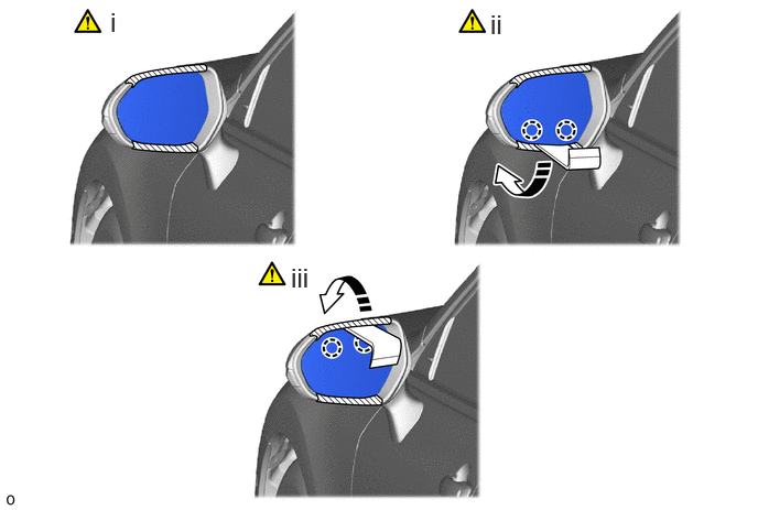

|
Move in this Direction | - | - |
Apply protective tape to the areas shown in the illustration.
Using a moulding remover D, detach the claw on the lower part of the outer mirror LH as shown in the illustration.
- NOTICE:
-
Do not forcibly pull on the outer mirror LH as the unit drive may detach, or the mirror surface part may break.
Using a moulding remover D, detach the claw on the upper part of the outer mirror LH as shown in the illustration.
- HINT:
-
The claw will reattach if excessive force is applied when pushing down the mirror surface.
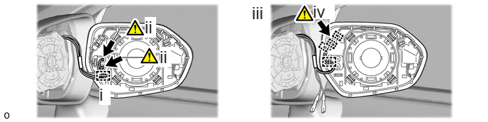
Detach the clamp.
Disconnect the 2 mirror heater connectors.
- NOTICE:
- ·
Do not raise the claw higher than is necessary as it will damage the claw of the terminal.
·If the claw of the connector is damaged, replace the outer mirror LH with a new one.
·If there is damage to the wire harness or an open circuit has occurred, replace the outer rear view mirror assembly LH with a new one.
Detach the clamp.
Disconnect the blind spot monitor indicator connector to remove the outer mirror LH.
- NOTICE:
- ·
If the connector is damaged, replace the outer mirror LH with a new one.
·If there is damage to the wire harness or an open circuit has occurred, replace the outer rear view mirror assembly LH with a new one.