Home › Vehicle Interior › LIGHTING (INT) › LIGHTING SYSTEM
RM37H0E _58 Vehicle Interior _095306 LIGHTING (INT) _0448415 LIGHTING SYSTEM J

LIGHTING (INT)  LIGHTING SYSTEM  Footwell Light Circuit  


DESCRIPTION

The main body ECU (multiplex network body ECU) controls the operation of the following lights:

·

No. 1 interior illumination light assembly LH (front footwell light)

·

No. 1 interior illumination light assembly RH (front footwell light)


WIRING DIAGRAM
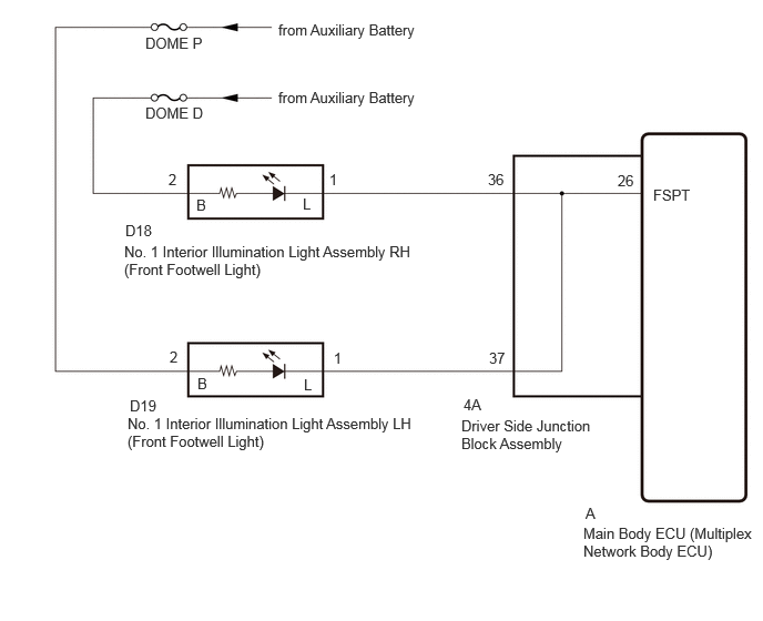
E456338E01
2.615,0.198 4.396,0.531 1.781,0.333 10 false from Auxiliary Battery 2.615,0.833 4.188,1.177 1.573,0.344 10 false from Auxiliary Battery 5.479,4.927 7.156,5.323 1.677,0.396 10 false Main Body ECU (Multiplex Network Body ECU) 4.333,3.917 5.583,4.323 1.25,0.406 10 false Driver Side Junction Block Assembly 6.135,1.75 6.75,1.948 0.615,0.198 10 false FSPT 5.5,4.74 5.656,4.938 0.156,0.198 10 false A 5.802,1.615 6.115,1.813 0.313,0.198 10 false 26 4.354,3.719 4.667,3.917 0.313,0.198 10 false 4A 1.365,0.979 2.281,1.177 0.917,0.198 10 false DOME D 1.365,0.323 2.281,0.521 0.917,0.198 10 false DOME P 1.177,2.083 1.635,2.281 0.458,0.198 10 false D18 1.219,3.729 1.677,3.927 0.458,0.198 10 false D19 1.198,3.896 3.917,4.271 2.719,0.375 10 false No. 1 Interior Illumination Light Assembly LH (Front Footwell Light) 1.167,2.281 3.927,2.635 2.76,0.354 10 false No. 1 Interior Illumination Light Assembly RH (Front Footwell Light) 4.583,1.604 4.896,1.802 0.313,0.198 10 false 36 4.594,3.281 4.906,3.479 0.313,0.198 10 false 37 1.583,1.604 1.74,1.802 0.156,0.198 10 false 2 1.844,1.844 2,2.042 0.156,0.198 10 false B 2.844,1.833 3,2.031 0.156,0.198 10 false L 3.094,1.604 3.25,1.802 0.156,0.198 10 false 1 1.594,3.271 1.75,3.469 0.156,0.198 10 false 2 3.135,3.281 3.292,3.479 0.156,0.198 10 false 1 1.854,3.521 2.01,3.719 0.156,0.198 10 false B 2.854,3.531 3.01,3.729 0.156,0.198 10 false L

CAUTION / NOTICE / HINT

NOTICE:
·

Inspect the fuses for circuits related to this system before performing the following procedure.

·

Before replacing the main body ECU (multiplex network body ECU), refer to Service Bulletin.


PROCEDURE

1.PERFORM ACTIVE TEST USING GTS
a.

Perform the Active Test according to the display on the GTS.

Body Electrical > Main Body > Active Test
Tester Display Measurement Item Control Range Diagnostic Note
Fr Foot Light Operation of the following lights:
·

No. 1 interior illumination light assembly LH (front footwell light)

·

No. 1 interior illumination light assembly RH (front footwell light)


OFF or ON -
Body Electrical > Main Body > Active Test
Tester Display
Fr Foot Light
50004 123 11
OK:

No. 1 Interior illumination light assembly (front footwell light) turns on or off.


Result:
Proceed to
OK
NG


OK

PROCEED TO NEXT SUSPECTED AREA SHOWN IN PROBLEM SYMPTOMS TABLE

NG

2.CHECK DRIVER SIDE JUNCTION BLOCK ASSEMBLY
a.

Remove the driver side junction block assembly.

Click herePower Source / Network>POWER DISTRIBUTION>MAIN BODY ECU>REMOVAL
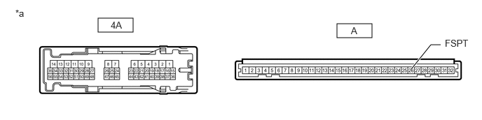
E361166C43
1.458,0.271 1.979,0.479 0.521,0.208 5.01,0.354 5.531,0.563 0.521,0.208 6.115,1.031 6.406,0.667 6.406,0.667 6.552,0.667 true 0.229,0.115 0.542,0.271 0.313,0.156 10 false *a 5.219,0.375 5.375,0.531 0.156,0.156 10 false A 1.646,0.292 1.917,0.479 0.271,0.188 10 false 4A 6.615,0.563 7.156,0.844 0.542,0.281 10 false FSPT
*a Component without harness connected
(Driver Side Junction Block Assembly)
- -


b.

Remove the main body ECU (multiplex network body ECU) from the driver side junction block assembly.

Click herePower Source / Network>POWER DISTRIBUTION>MAIN BODY ECU>REMOVAL


c.

Measure the resistance according to the value(s) in the table below.

Standard Resistance:
Tester Connection Condition Specified Condition
4A-36 - A-26 (FSPT) Always Below 1 Ω


Result:
Proceed to
OK
NG


OK

REPLACE MAIN BODY ECU (MULTIPLEX NETWORK BODY ECU)

NG

REPLACE DRIVER SIDE JUNCTION BLOCK ASSEMBLY