INTAKE / EXHAUST EXHAUST PIPE INSTALLATION
CAUTION / NOTICE / HINT
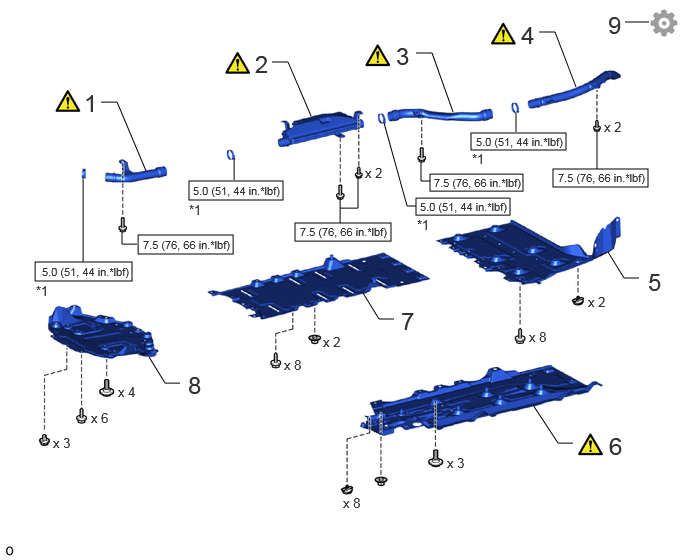
| Procedure | Part Name Code | 
|

|

|
|
|---|---|---|---|---|---|
| 1 | NO. 1 FC EXHAUST PIPE | 17DB1 | ( ) |
- | - |
| 2 | FC EXHAUST TAILPIPE ASSEMBLY | 17DB0 | ()
|
- | - |
| 3 | NO. 2 FC EXHAUST PIPE | 17DB2 | ()
|
- | - |
| 4 | NO. 3 FC EXHAUST PIPE | 17DB3 | ()
|
- | - |
| 5 | REAR FLOOR SIDE MEMBER COVER LH | 57628E | - | - | - |
| 6 | NO. 2 FLOOR BOARD SUB-ASSEMBLY | 58402K | ()
|
- | - |
| 7 | REAR NO. 3 FLOOR BOARD SUB-ASSEMBLY | 58403L | - | - | - |
| 8 | REAR NO. 4 FLOOR BOARD SUB-ASSEMBLY | 58404B | - | - | - |
| 9 | INSPECT FOR EXHAUST GAS LEAK | - | - | - | ()
|
| *1 | HOSE CLAMP | - | - |

|
N*m (kgf*cm, ft.*lbf): Specified torque | - | - |
PROCEDURE

 17DB1
1.INSTALL NO. 1 FC EXHAUST PIPE
|
|
|
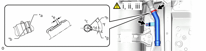
| *a | Mark of Pipe | *b | Mark of Hose |
| *c | Upper Side of Vehicle | *d | RH Side of Vehicle |
| *e | 0 to 10 mm (0 to 0.394 in.) | *f | Area of Bolt of Hose Clamp |
| *g | 15° | *h | 55° |
Connect the No. 1 FC exhaust pipe to the FC stack air outlet hose with the bolt as shown in the illustration.
- Torque:
- 7.5 N*m (76 kgf*cm, 66 in.*lbf)
Tighten the hose clamp as shown in the illustration.
- Torque:
- 5.0 N*m (51 kgf*cm, 44 in.*lbf)
Try to move the clamp by hand and confirm that it does not rotate.
17DB0
2.INSTALL FC EXHAUST TAILPIPE ASSEMBLY
|
|
|
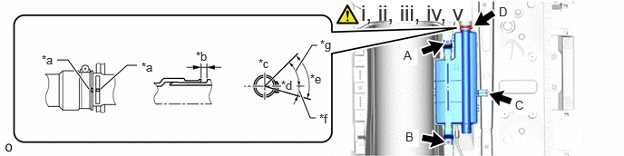
| *a | Groove of Pipe | *b | 0 to 10 mm (0 to 0.394 in.) |
| *c | Upper Side of Vehicle | *d | RH Side of Vehicle |
| *e | Area of Bolt of Hose Clamp | *f | 15° |
| *g | 55° | - | - |
Temporarily install the FC exhaust tailpipe assembly to the No. 1 FC exhaust pipe with the bolt A as shown in the illustration.
Tighten the 2 bolts in the order shown B and A.
- Torque:
- 7.5 N*m (76 kgf*cm, 66 in.*lbf)
Tighten the bolt C.
- Torque:
- 7.5 N*m (76 kgf*cm, 66 in.*lbf)
Tighten the hose clamp D as shown in the illustration.
- Torque:
- 5.0 N*m (51 kgf*cm, 44 in.*lbf)
Try to move the clamp by hand and confirm that it does not rotate.
17DB2
3.INSTALL NO. 2 FC EXHAUST PIPE
|
|
|
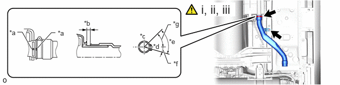
| *a | Groove of Pipe | *b | 0 to 10 mm (0 to 0.394 in.) |
| *c | Upper Side of Vehicle | *d | RH Side of Vehicle |
| *e | Area of Bolt of Hose Clamp | *f | 15° |
| *g | 55° | - | - |
Install the No. 2 FC exhaust pipe to the FC exhaust tailpipe assembly with the bolt as shown in the illustration.
- Torque:
- 7.5 N*m (76 kgf*cm, 66 in.*lbf)
Tighten the hose clamp as shown in the illustration.
- Torque:
- 5.0 N*m (51 kgf*cm, 44 in.*lbf)
Try to move the clamp by hand and confirm that it does not rotate.
17DB3
4.INSTALL NO. 3 FC EXHAUST PIPE
|
|
|
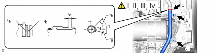
| *a | Groove of Pipe | *b | Mark of Pipe |
| *c | Upper Side of Vehicle | *d | RH Side of Vehicle |
| *e | 0 to 10 mm (0 to 0.394 in.) | *f | Area of Bolt of Hose Clamp |
| *g | 15° | *h | 55° |
Temporarily install the No. 3 FC exhaust pipe to the No. 2 FC exhaust pipe with the bolt A as shown in the illustration.
Tighten the 2 bolts in the order shown B and A.
- Torque:
- 7.5 N*m (76 kgf*cm, 66 in.*lbf)
Tighten the hose clamp C as shown in the illustration.
- Torque:
- 5.0 N*m (51 kgf*cm, 44 in.*lbf)
Try to move the clamp by hand and confirm that it does not rotate.
57628E
5.INSTALL REAR FLOOR SIDE MEMBER COVER LH
58402K
6.INSTALL NO. 2 FLOOR BOARD SUB-ASSEMBLY
|
|
Click here()
|
58403L
7.INSTALL REAR NO. 3 FLOOR BOARD SUB-ASSEMBLY
58404B
8.INSTALL REAR NO. 4 FLOOR BOARD SUB-ASSEMBLY
9.INSPECT FOR EXHAUST GAS LEAK
If gas is leaking, tighten the areas necessary to stop the leak. Replace damaged parts as necessary.