Home › Engine / Hybrid System › INTAKE / EXHAUST › AIR BYPASS VALVE
RM37H0E _51 Engine / Hybrid System _095594 INTAKE / EXHAUST _0448990 AIR BYPASS VALVE A

INTAKE / EXHAUST  AIR BYPASS VALVE  INSTALLATION  


CAUTION / NOTICE / HINT
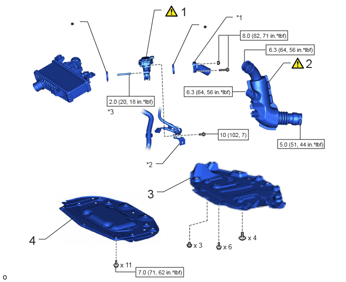
COMPONENTS (INSTALLATION)
A478619N02
4.521,2.677 5.146,2.896 0.625,0.219 2.219,1.99 3.198,2.198 0.979,0.208 4.979,0.635 5.958,0.833 0.979,0.198 5.51,0.927 6.51,1.135 1,0.208 5.75,2.885 6.719,3.073 0.969,0.188 3.813,1.792 4.813,2 1,0.208 2.813,5.531 3.802,5.729 0.99,0.198 5.573,1.688 5.875,1.302 5.875,1.302 6.021,1.302 false 3.031,1.167 3.198,0.208 3.198,0.208 3.344,0.208 false 3.594,1.333 3.979,0.51 3.979,0.51 4.125,0.51 false 2.198,1.479 1.813,0.448 1.813,0.448 1.656,0.448 false 3.229,3.385 3.365,3.385 3.365,3.385 3.719,2.969 false 4.031,1.271 4.688,0.354 4.688,0.354 4.823,0.354 false 2.677,1.99 2.677,1.542 false 4.729,1.396 4.729,0.74 false 4.531,1.271 4.531,0.729 4.531,0.729 4.969,0.729 false 4.813,1.896 5.083,1.896 false 6.219,2.885 6.219,2.573 false 5.063,1.271 5.063,1.031 5.063,1.031 5.5,1.031 false 3.25,3.969 3.385,3.969 3.385,3.969 3.948,3.677 false 0.802,4.948 0.938,4.948 0.938,4.948 1.5,4.521 false 4.25,2.771 4.521,2.771 false 2.396,5.531 2.396,5.625 2.396,5.625 2.802,5.625 false 3.74,0.094 4.052,0.417 0.313,0.323 18 false 1 3.052,3.865 3.365,4.188 0.313,0.323 18 false 3 6.333,1.167 6.646,1.49 0.313,0.323 18 false 2 4.896,0.281 5.281,0.594 0.385,0.313 10 false *1 3.031,3.323 3.417,3.635 0.385,0.313 10 false *2 2.229,2.229 2.615,2.542 0.385,0.313 10 false *3 4.208,0.458 4.771,0.792 0.563,0.333 10 false ● 1.458,0.396 1.969,0.667 0.51,0.271 10 false ● 2.26,2.031 3.24,2.219 0.979,0.188 8 false 2.0 (20, 18 in.*lbf) 5.021,0.667 6.063,0.854 1.042,0.188 8 false 8.0 (82, 71 in.*lbf) 4.552,2.719 5.531,2.938 0.979,0.219 8 false 10 (102, 7) 5.792,2.917 6.813,3.094 1.021,0.177 8 false 5.0 (51, 44 in.*lbf) 5.573,0.958 6.615,1.135 1.042,0.177 8 false 6.3 (64, 56 in.*lbf) 0.604,4.823 0.917,5.146 0.313,0.323 18 false 4 4.01,4.99 4.323,5.188 0.313,0.198 10 false x 3 5.135,4.833 5.448,5.031 0.313,0.198 10 false x 4 4.625,5.021 4.938,5.219 0.313,0.198 10 false x 6 2.49,5.396 2.802,5.594 0.313,0.198 10 false x 11 2.865,5.563 3.885,5.75 1.021,0.188 8 false 7.0 (71, 62 in.*lbf) 3.865,1.833 4.906,2.01 1.042,0.177 8 false 6.3 (64, 56 in.*lbf)

Procedure Part Name Code
Z101186

Z101188

Z101187

1 FC AIR BY-PASS VALVE ASSEMBLY 17C90 (Click here) - -
2 FC STACK AIR OUTLET HOSE ASSEMBLY 17D10 (Click here) - -
3 REAR NO. 4 FLOOR BOARD SUB-ASSEMBLY 58404B - - -
4 FRONT COMPARTMENT UNDER COVER ASSEMBLY 51420A - - -

*1 FC AIR BY-PASS VALVE PIPE ASSEMBLY *2 WIRE HARNESS CLAMP BRACKET
*3 STUD BOLT - -
V100146

N*m (kgf*cm, ft.*lbf): Specified torque ● Non-reusable part

PROCEDURE

Hide 17C90 1.INSTALL FC AIR BY-PASS VALVE ASSEMBLY
a.
A478622C01
1.167,0.906 1.302,0.906 1.302,0.906 1.594,1.167 true 4.594,0.177 4.708,0.177 4.708,0.177 5.094,0.323 true 0.979,0.833 1.219,1.01 0.24,0.177 10 true *a 0.406,0.063 0.708,0.344 0.302,0.281 18 false i 4.375,0.104 4.615,0.281 0.24,0.177 10 true *a
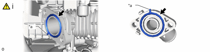
*a Protrusion - -


i.

Install the 2 FC air by-pass valve pipe gaskets to the intercooler with sensor assembly and FC air by-pass valve pipe assembly with the protrusions of the FC air by-pass valve pipe gasket oriented as shown in the illustration.


b.
A478621N01
4.875,0.042 5.417,0.313 0.542,0.271 18 true iii, iv 0.104,0.031 0.313,0.323 0.208,0.292 18 true i 2.885,0.031 3.094,0.323 0.208,0.292 18 true ii 3.958,1.313 4.094,1.5 0.135,0.188 10 true 1 3.188,0.25 3.333,0.406 0.146,0.156 10 true 2

i.

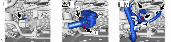
Using an E7 "TORX" socket wrench, install the stud bolt to the intercooler with sensor assembly.

Torque:
2.0 N*m (20 kgf*cm, 18 in.*lbf)


ii.

Install the FC air by-pass valve assembly and FC air by-pass valve pipe assembly with the bolt and nut in the order shown in the illustration.

Torque:
8.0 N*m (82 kgf*cm, 71 in.*lbf)


iii.

Install the wire harness clamp bracket to the FC air by-pass valve assembly with the bolt.

Torque:
10 N*m (102 kgf*cm, 7 ft.*lbf)


iv.

Connect the 2 connectors and 3 clamps.


Hide 17D10 2.INSTALL FC STACK AIR OUTLET HOSE ASSEMBLY
a.
A481232C01
5.708,1.104 5.927,1.333 5.927,1.333 6.073,1.333 false 5.25,1.229 5.448,1.469 5.448,1.469 5.594,1.469 false 5.656,1.396 5.969,1.552 0.313,0.156 10 false *1 6.115,1.26 6.427,1.417 0.313,0.156 10 false *2 0.375,0.063 0.656,0.344 0.281,0.281 18 false i
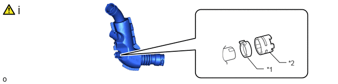
*1 Hose Clip *2 Water Hose Set


i.

Install the hose clip and water hose set to the FC stack air outlet hose assembly as shown in the illustration.


b.
A478546C01
6.021,0.979 6.354,0.979 true 5.344,1.073 5.625,1.323 5.625,1.323 5.729,1.323 true 0.396,1.313 0.5,1.313 0.5,1.313 0.719,1.021 true 0.448,0.479 0.552,0.479 0.552,0.479 0.74,0.99 true 1.375,1.323 1.479,1.323 1.479,1.323 1.802,1.042 true 1.417,0.615 1.521,0.615 1.521,0.615 1.792,0.917 true 0.927,3.063 1.083,2.625 1.083,2.625 1.188,2.625 true 0.49,3.469 0.594,3.469 0.594,3.469 0.813,3.125 true 4.99,1.333 5.063,1.333 5.063,1.333 5.281,1.042 true 6.25,2.427 6.354,2.427 6.354,2.427 6.469,2.823 true 6.052,3.292 6.156,3.292 6.156,3.292 6.406,2.875 true 5.563,2.813 5.667,2.646 5.667,2.646 5.771,2.646 true 4.979,2.698 5.083,2.698 5.083,2.698 5.354,2.833 true 6.5,0.969 6.604,0.802 6.604,0.802 6.708,0.802 true 2.99,2.948 3.115,2.688 3.115,2.688 3.177,2.688 true 3.021,3.167 3.094,3.458 3.094,3.458 3.156,3.458 true 0.25,0.385 0.542,0.573 0.292,0.188 10 false *a 0.229,1.24 0.542,1.427 0.313,0.188 10 false *b 1.25,2.552 1.563,2.708 0.313,0.156 10 false *c 0.313,3.406 0.625,3.563 0.313,0.156 10 false *d 6.052,2.333 6.354,2.5 0.302,0.167 10 false *e 4.813,2.625 5.031,2.802 0.219,0.177 10 false *f 4.813,1.24 5.125,1.438 0.313,0.198 10 false *g 6.354,1.302 6.667,1.458 0.313,0.156 10 false *h 2.573,2.76 2.771,2.917 0.198,0.156 10 false *i 2.854,2.99 2.979,3.177 0.125,0.188 10 true *j 1.583,2.625 1.896,2.833 0.313,0.208 10 false *k 3.146,2.906 3.458,3.063 0.313,0.156 10 false *l 3.188,3.375 3.5,3.531 0.313,0.156 10 true *m 3.24,2.604 3.552,2.76 0.313,0.156 10 true *o 1.219,0.531 1.458,0.708 0.24,0.177 10 false *a 1.188,1.24 1.479,1.427 0.292,0.188 10 false *b 5.781,1.24 6.094,1.396 0.313,0.156 10 false *a 5.875,3.198 6.188,3.396 0.313,0.198 10 false *g 5.813,2.552 6.125,2.75 0.313,0.198 10 false *g 6.74,0.729 7.052,0.885 0.313,0.156 10 false *a 5.854,0.885 6.146,1.104 0.292,0.219 10 false *g 1.708,1.479 2.021,1.635 0.313,0.156 10 false *n 3.99,0.229 4.135,0.396 0.146,0.167 10 true A 4.094,0.896 4.229,1.063 0.135,0.167 10 true A 2.792,1.74 2.927,1.917 0.135,0.177 10 true B 2.76,0.135 2.958,0.417 0.198,0.281 18 true i
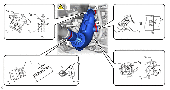
*a Protrusion of Pipe *b Groove of Hose
*c Mark of Pipe *d Mark of Hose
*e Rib of Pipe *f Area of Claw Center of Hose Clip
*g Hose Paint Mark *h Maximum Misalignment Width (paint mark makes contact with protrusion)
*i Upper Side of Vehicle *j RH Side of Vehicle
*k 0 to 10 mm (0 to 0.394 in.) *l Area of Bolt of Hose Clamp
*m 15° *n Maximum Misalignment Width (groove of hose makes contact with protrusion of pipe )
*o 55° - -


i.

Connect the FC stack air outlet hose with the hose clamp and hose clip as shown in the illustration.

Torque:
for hose clamp A : 6.3 N*m (64 kgf*cm, 56 in.*lbf)
for hose clamp B : 5.0 N*m (51 kgf*cm, 44 in.*lbf)


Hide 58404B 3.INSTALL REAR NO. 4 FLOOR BOARD SUB-ASSEMBLY

Hide 51420A 4.INSTALL FRONT COMPARTMENT UNDER COVER ASSEMBLY