INTAKE / EXHAUST AIR COMPRESSOR REASSEMBLY
CAUTION / NOTICE / HINT
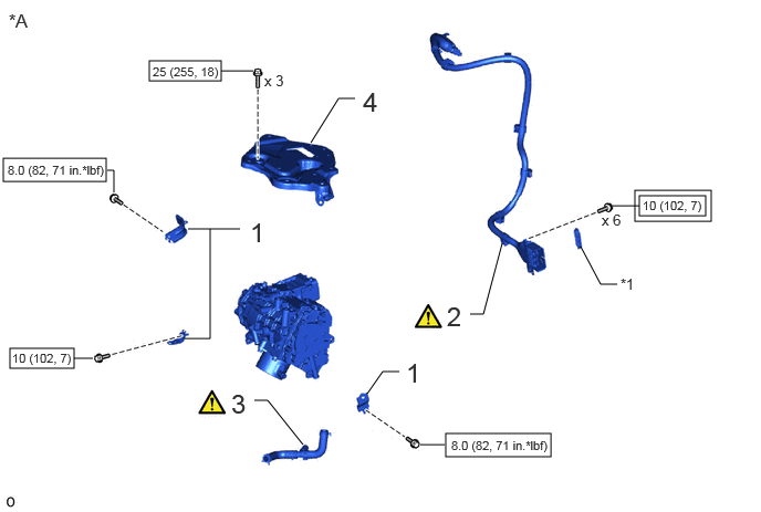
| Procedure | Part Name Code | 
|

|

|
|
|---|---|---|---|---|---|
| 1 | BRACKET | - | - | - | - |
| 2 | FC AIR COMPRESSOR MOTOR CABLE ASSEMBLY | 17A90 | ( ) |
- | - |
| 3 | FC AIR COMPRESSOR COOLING WATER HOSE WITH JOINT ASSEMBLY | 17A40 | ()
|
- | - |
| 4 | FC AIR COMPRESSOR BRACKET | 17AA1 | - | - | - |
| *A | for LHD | - | - |
| *1 | MOTOR CABLE TERMINAL CAP | - | - |

|
Tightening torque for "Major areas involving basic vehicle performance such as moving/turning/stopping": N*m (kgf*cm, ft.*lbf) | 
|
N*m (kgf*cm, ft.*lbf): Specified torque |
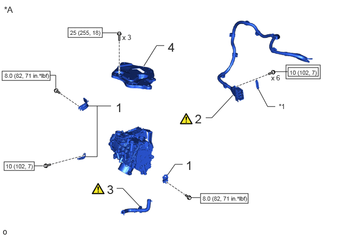
| Procedure | Part Name Code |
|
|
|
|
|---|---|---|---|---|---|
| 1 | BRACKET | - | - | - | - |
| 2 | FC AIR COMPRESSOR MOTOR CABLE ASSEMBLY | 17A90 | ()
|
- | - |
| 3 | FC AIR COMPRESSOR COOLING WATER HOSE WITH JOINT ASSEMBLY | 17A40 | ()
|
- | - |
| 4 | FC AIR COMPRESSOR BRACKET | 17AA1 | - | - | - |
| *A | for RHD | - | - |
| *1 | MOTOR CABLE TERMINAL CAP | - | - |
|
|
Tightening torque for "Major areas involving basic vehicle performance such as moving/turning/stopping": N*m (kgf*cm, ft.*lbf) |
|
N*m (kgf*cm, ft.*lbf): Specified torque |
PROCEDURE

 1.INSTALL BRACKET
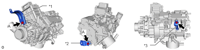
| *1 | FC Air Compressor Cable Bracket | *2 | No. 1 FC Inverter Cooling Bracket |
| *3 | Wire Harness Clamp Bracket | - | - |
- Torque:
- for bolt A : 8.0 N*m (82 kgf*cm, 71 in.*lbf)
- for bolt B : 10 N*m (102 kgf*cm, 7 ft.*lbf)
17A90
2.INSTALL FC AIR COMPRESSOR MOTOR CABLE ASSEMBLY
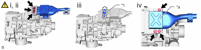
| *1 | Motor Cable Terminal Cap | - | - |
| *a | Shell Part | - | - |
Connect the clamp.
Install the FC air compressor motor cable assembly to the FC air compressor with motor assembly with the 3 bolts.
- Torque:
- 10 N*m (102 kgf*cm, 7 ft.*lbf)
- NOTICE:
- ·
To prevent damage to the threaded portion, be sure to perform the work by hand.
·Do not touch the rubber seal or terminal portion of the connector.
·When connecting, do not damage or scratch the terminal portions, connector housing, or FC air compressor with motor assembly.
Engage the 2 claws and install the motor cable terminal cap.
Install the shell part to the FC air compressor with motor assembly with the 3 bolts.
- Torque:
- 10 N*m (102 kgf*cm, 7 ft.*lbf)
17A40
3.INSTALL FC AIR COMPRESSOR COOLING WATER HOSE WITH JOINT ASSEMBLY
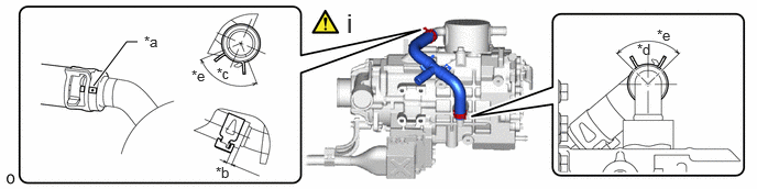
| *a | Hose Paint Mark | *b | 2 to 5 mm (0.0787 to 0.197 in.) |
| *c | Lower Side of Vehicle | *d | Rear Side of Vehicle |
| *e | 90° | - | - |
Connect the FC air compressor cooling water hose with joint assembly to the FC air compressor with motor assembly and slide the 2 hose clips to secure it.
- NOTICE:
-
Make sure to position the hose clip as shown in the illustration.
17AA1
4.INSTALL FC AIR COMPRESSOR BRACKET
- Torque:
- 25 N*m (255 kgf*cm, 18 ft.*lbf)