STEERING COLUMN STEERING COLUMN ASSEMBLY(for Manual Tilt and Manual Telescopic Steering Column) DISASSEMBLY
CAUTION / NOTICE / HINT
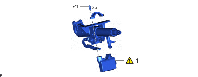
| Procedure | Part Name Code | 
|

|

|
|
|---|---|---|---|---|---|
| 1 | UPPER STEERING LOCK ACTUATOR OR BRACKET ASSEMBLY | 45020B | ( ) |
- | - |
| *1 | STEERING LOCK SET BOLT | - | - |
| ● | Non-reusable part | - | - |
CAUTION / NOTICE / HINT
- NOTICE:
- ·
Do not drop the upper steering lock actuator or bracket assembly, strike it with tools or subject it toimpacts.
·If the upper steering lock actuator or bracket assembly is subjected to an impact, replace it with a newone.
PROCEDURE

 45020B
1.REMOVE UPPER STEERING LOCK ACTUATOR OR BRACKET ASSEMBLY
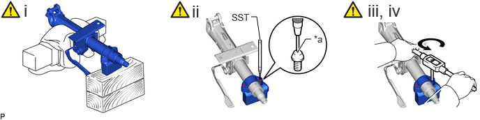
| *a | Center of the steering lock set bolt | - | - |
Secure the steering column assembly in a vise between aluminum plates.
- NOTICE:
- ·
Do not overtighten the vise.
·Do not clamp the upper steering lock actuator or bracket assembly in the vise.
Using SST, strike a punch mark for drilling in the center of the steering lock set bolt.
- SST
- 09622-00010
- NOTICE:
-
When striking the punch mark, in order to prevent impact force from being applied to the upper steering lock actuator or bracket assembly, do not use a normal center punch.
Using a drill, drill a hole in 2 steering lock set bolts and insert a screw extractor.
Using the screw extractor, remove the 2 steering lock set bolts and upper steering lock actuator or bracket assembly.
- NOTICE:
-
Push in the screw extractor by hand, and do not strike it with tools, etc.