RM37H0E
_55
Steering
_095770
STEERING COLUMN
_0449641
STEERING COLUMN ASSEMBLY(for Manual Tilt and Manual Telescopic Steering Column)
A
STEERING COLUMN STEERING COLUMN ASSEMBLY(for Manual Tilt and Manual Telescopic Steering Column) REASSEMBLY
CAUTION / NOTICE / HINT
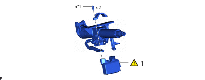
COMPONENTS (REASSEMBLY)
4.156,2.198 4.49,2.198
true
2.896,0.229 3.229,0.229
true
4.896,2.063 5.167,2.354
0.271,0.292
18
false
1
2.625,0.146 2.969,0.396
0.344,0.25
10
false
●*1
3.344,0.177 3.698,0.427
0.354,0.25
10
false
x 2
| Procedure | Part Name Code | 
|

|

|
|
|---|---|---|---|---|---|
| 1 | STEERING LOCK ACTUATOR OR UPPER BRACKET ASSEMBLY | 45020B | ( ) |
- | - |
| *1 | STEERING LOCK SET BOLT | - | - |
| ● | Non-reusable part | - | - |
CAUTION / NOTICE / HINT
- NOTICE:
- ·
Do not drop the upper steering lock actuator or bracket assembly, strike it with tools or subject it toimpacts.
·If the upper steering lock actuator or bracket assembly is subjected to an impact, replace it with a newone.
PROCEDURE

 45020B
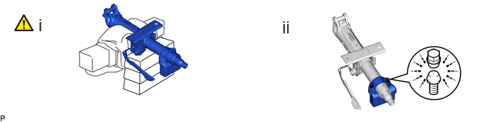
1.INSTALL UPPER STEERING LOCK ACTUATOR OR BRACKET ASSEMBLY
|
|
|
a.
0.563,0.219 0.813,0.573
0.25,0.354
18
false
i
4.135,0.25 4.385,0.604
0.25,0.354
18
false
ii
i.
Secure the steering column assembly in a vise between aluminum plates.
- NOTICE:
- ·
Do not overtighten the vise.
·Do not clamp the upper steering lock actuator or bracket assembly in the vise.
ii.
Install the upper steering lock actuator or bracket assembly with 2 new steering lock set bolts, and tighten the bolts until they break off.