EXTERIOR PANELS / TRIM REAR BUMPER REMOVAL
CAUTION / NOTICE / HINT
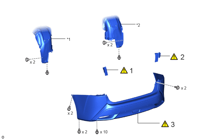
| Procedure | Part Name Code | 
|

|

|
|
|---|---|---|---|---|---|
| 1 | REAR COMBINATION LIGHT COVER LH | 81498 | ( ) |
- | - |
| 2 | REAR COMBINATION LIGHT COVER RH | 81497 | ()
|
- | - |
| 3 | REAR BUMPER ASSEMBLY | - | ()
|
- | - |
| *1 | REAR WHEEL HOUSE LINER LH | *2 | REAR WHEEL HOUSE LINER RH |
CAUTION / NOTICE / HINT
The necessary procedures (adjustment, calibration, initialization or registration) that must be performed after parts are removed, installed or replaced during the rear bumper assembly removal/installation are shown below.
| Replaced Part or Performed Procedures | Necessary Procedures | Effect/Inoperative Function when Necessary Procedures are not Performed | Link |
|---|---|---|---|
·
Ultrasonic sensor (Including removal and installation) ·
Rear bumper assembly (Including removal and installation) |
·
Measurement of ultrasonic sensor detection angle ·
Ultrasonic sensor detection angle registration |
·
TOYOTA Parking assist- sensor system ·
Parking support brake system ·
Advanced park |
w/ Advanced Park:
( )
w/o Advanced Park: ( )
|
PROCEDURE

 81498
1.REMOVE REAR COMBINATION LIGHT COVER LH
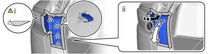

|
Place hands here | 
|
Remove in this Direction (1) |

|
Remove in this Direction (2) | - | - |
Put protective tape around the rear combination light cover LH.
Detach the clip and remove the rear combination light cover LH.
81497
2.REMOVE REAR COMBINATION LIGHT COVER RH
|
|
Use the same procedure described for the LH side. |
3.REMOVE REAR BUMPER ASSEMBLY
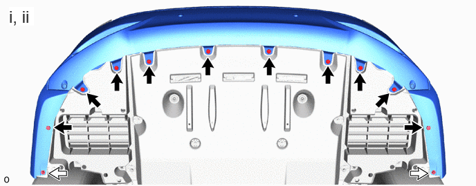

|
Clip | 
|
Screw |
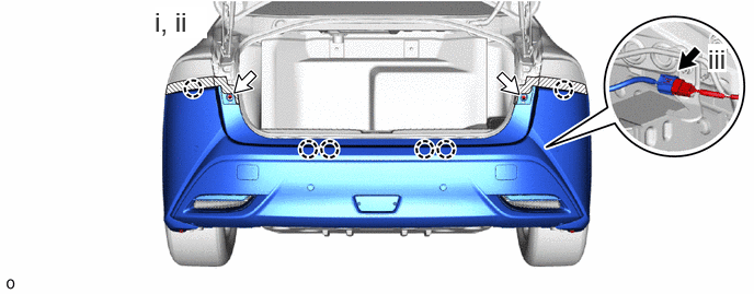
Remove the 10 clips.
Remove the 2 screws.
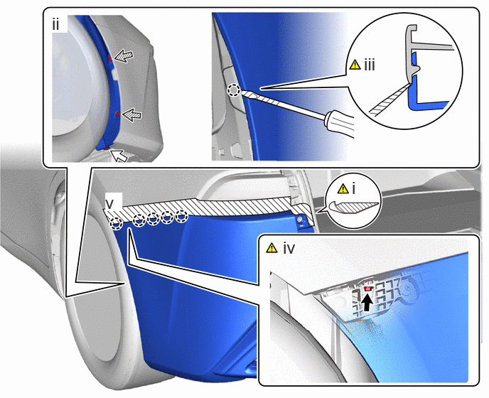
|
|
Screw |
|
Clip |

|
Grommet | - | - |
Put protective tape around the rear bumper assembly.
Remove the clip and 2 grommets.
Using a screwdriver, detach the claw as shown in the illustration.
- HINT:
-
Tape the screwdriver tip before use.
Fold back the rear wheel house liner LH and remove the screw.
Detach the claw.
Use the same procedure for the other side.
|
|
Connector |
|
Screw |
Remove the 2 screws.
Detach the claw and remove the rear bumper assembly.
Disconnect the connector.