HEATING / AIR CONDITIONING AIR CONDITIONING SYSTEM TERMINALS OF ECU
AIR CONDITIONING AMPLIFIER ASSEMBLY
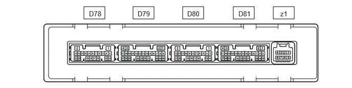
Disconnect the D79 and D81 air conditioning amplifier assembly connectors.
Measure the voltage and resistance according to the value(s) in the table below.
| Terminal No.
(Symbol) |
Terminal Description | Condition | Specified Condition |
|---|---|---|---|
| D81-5 (B) - Body ground | Power source (Back-up) | Ignition switch off | 11 to 14 V |
| D81-6 (IG+) - Body ground | Power source (IG) | Ignition switch ON | 11 to 14 V |
| Ignition switch off | Below 1 V | ||
| D81-17 (GND) - Body ground | Ground | Always | Below 1 Ω |
| D79-18 (SGND) - Body ground | Ground | Always | Below 1 Ω |
Reconnect the D79 and D81 air conditioning amplifier assembly connectors.
Measure the voltage, resistance and check for pulse according to the value(s) in the table below.
| Terminal No.
(Symbol) |
Terminal Description | Condition | Specified Condition |
|---|---|---|---|
| D78-1 (SG-6) - Body ground | Ground of three-way valve | Always | Below 1 Ω |
| D78-2 (S5-4) - Body ground | Power source (three-way valve) | Ignition switch off → ON | Below 1 V → 4.75 to 5.25 V |
| D78-6 (PO1) - D78-1 (SG-6) | Heater water valve assembly power input signal | ·
Ignition switch ON ·
Heater water valve assembly mode single |
3.65 to 4.05 V |
·
Ignition switch ON ·
Heater water valve assembly mode combination |
0.95 to 1.35 V | ||
| D78-17 (WP) - Body ground | Hater with motor pump assembly operation signal | ·
Ignition switch ON ·
Set temperature MAX HOT ·
Blower speed LO or higher |
Pulse generation
(See waveform 5) |
| D78-20 (MP2+) - Body ground | Three-way valve output signal | ·
Ignition switch ON ·
Three-way valve mode combination → single |
Below 1 V → 11 to 14 V → Belwo 1 V |
| D78-21 (MP2-) - Body ground | Three-way valve output signal | ·
Ignition switch ON ·
Three-way valve mode single → combination |
Below 1 V → 11 to 14 V → Belwo 1 V |
| D79-5 (SIG1) - Body ground | Relay signal | ·
Ignition switch ON ·
Blower switch: LO ·
A/C switch: ON |
Below 1 Ω |
| D79-20 (RLIN) - Body ground*2 | LIN communication line | Ignition switch ON | Pulse generation
(See waveform 1) |
| D80-1 (TAM) - D80-14 (SG-2) | Ambient temperature sensor signal | ·
Ignition switch ON (do not start the engine and electric motor) ·
Ambient temperature: 25°C (77°F) |
1.05 to 1.45 V |
·
Ignition switch ON (do not start the engine and electric motor) ·
Ambient temperature: 40°C (104°F) |
0.64 to 0.87 V | ||
| D80-3 (SG-1) - Body ground | Ground for sensor | Always | Below 1 Ω |
| D80-5 (TR) - D80-3 (SG-1) | Room temperature sensor signal | ·
Ignition switch ON ·
Cabin temperature: 25°C (77°F) |
1.05 to 1.45 V |
| D80-6 (PRE) - D80-15 (SG-4) | Air conditioner pressure sensor signal | ·
Engine running ·
Air conditioning system operating ·
Refrigerant pressure: Normal pressure (below 3025 kPaG [30.8 kgf/cm2, 439 psi] and higher than 176 kPaG [1.8 kgf/cm2, 26 psi]) |
0.62 to 4.73 V*1 |
| D80-11 (S5-3) - Body ground | Power source (air conditioner pressure sensor) | Ignition switch off → ON | Below 1 V → 4.75 to 5.25 V |
| D80-12 (WIP) - Body ground | Hater with motor pump assembly operation signal | ·
Ignition switch ON ·
Set temperature MAX HOT ·
Blower speed LO or higher |
Pulse generation
(See waveform 4) |
| D80-14 (SG-2) - Body ground | Ground for sensor | Always | Below 1 Ω |
| D80-15 (SG-4) - Body ground | Ground for sensor | Always | Below 1 Ω |
| D81-1 (CANL) | CAN communication line | - | - |
| D81-2 (CANH) | CAN communication line | - | - |
| D81-7 (LIN1) - Body ground | LIN communication line | Ignition switch ON | Ignition switch ON
(See waveform 1) |
| D81-21 (BLW) - Body ground | Blower with fan motor assembly operation signal | ·
Ignition switch ON ·
Blower switch: LO |
Ignition switch ON
(See waveform 2) |
| z1-q (BUS G) - Body ground | Ground for BUS IC | Always | Below 1 Ω |
| z1-3 (BUS) - z1-2 (BUS G) | BUS IC control signal | Ignition switch ON | Pulse generation
(See waveform 3) |
| z1-4 (B BUS) - z1-2 (BUS G) | Power supply for BUS IC | Ignition switch off | 11 to 14 V |
| z1-5 (SGA) - Body ground | Ground for No. 1 cooler thermistor | Always | Below 1 Ω |
| z1-6 (TEA) - z1-5 (SGA) | No. 1 cooler thermistor signal | ·
Ignition switch ON ·
Evaporator temperature: 0°C (32°F) |
1.7 to 2.1 V |
·
Ignition switch ON ·
Evaporator temperature: 15°C (59°F) |
0.9 to 1.3 V |
*1: While sensor voltage is 5 V
*2: for 3 Zone
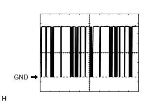
Waveform 1:
| Item | Content |
|---|---|
| Terminal No. | D79-20 (RLIN) - Body ground*
D81-7 (LIN1) - Body ground |
| Tool Setting | 2 V/DIV., 20 μs./DIV. |
| Vehicle Condition | Ignition switch ON |
*: for 3 Zone
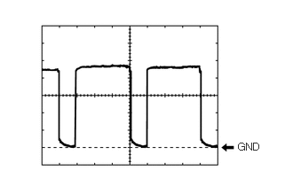
Waveform 2:
| Item | Content |
|---|---|
| Terminal No. | D81-21 (BLW) - Body ground |
| Tool Setting | 1 V/DIV., 500 μs./DIV. |
| Vehicle Condition | ·
Ignition switch ON ·
Blower switch: LO |
- HINT:
-
The waveform varies with the blower speed.
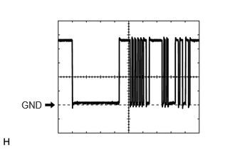
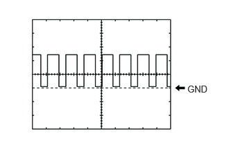
Waveform 3:
| Item | Content |
|---|---|
| Terminal No. | z1-3 (BUS) - z1-2 (BUSG) |
| Tool Setting | 2 V/DIV., 20 μs./DIV. |
| Vehicle Condition | Ignition switch ON |
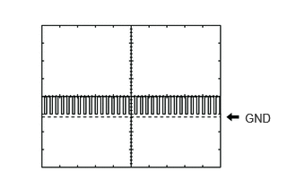
Waveform 4:
| Item | Content |
|---|---|
| Terminal No. | D80-12 (WIP) - Body ground |
| Tool Setting | 5 V/DIV., 100 ms./DIV. |
| Vehicle Condition | ·
Ignition switch ON ·
Set temperature MAX HOT ·
Blower speed LO or higher |
Waveform 5:
| Item | Content |
|---|---|
| Terminal No. | D78-17 (WP) - Body ground |
| Tool Setting | 5 V/DIV., 100 ms./DIV. |
| Vehicle Condition | ·
Ignition switch ON ·
Set temperature MAX HOT ·
Blower speed LO or higher |
AIR CONDITIONING CONTROL ASSEMBLY (w/ Navigation System)
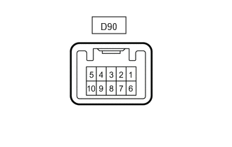
Disconnect the D90 air conditioning control assembly connector.
Measure the voltage and resistance according to the value(s) in the table below.
| Terminal No.
(Symbol) |
Terminal Description | Condition | Specified Condition |
|---|---|---|---|
| D90-4 (IG+) - Body ground | Power source (IG) | Ignition switch ON | 11 to 14 V |
| Ignition switch off | Below 1 V | ||
| D90-8 (E) - Body ground | Ground | Always | Below 1 Ω |
Reconnect the D90 air conditioning control assembly connector.
Check for pulse according to the value(s) in the table below.
| Terminal No.
(Symbol) |
Terminal Description | Condition | Specified Condition |
|---|---|---|---|
| D90-3 (LIN1) - Body ground | LIN communication line | Ignition switch ON | Ignition switch ON
(See waveform 1) |
Waveform 3:
| Item | Content |
|---|---|
| Terminal No. | D90-3 (LIN1) - Body ground |
| Tool Setting | 2 V/DIV., 20 μs./DIV. |
| Vehicle Condition | Ignition switch ON |
AIR CONDITIONING CONTROL ASSEMBLY (w/o Navigation System)
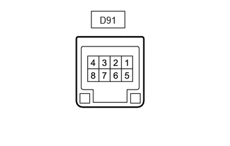
Disconnect the D91 air conditioning control assembly connector.
Measure the voltage and resistance according to the value(s) in the table below.
| Terminal No.
(Symbol) |
Terminal Description | Condition | Specified Condition |
|---|---|---|---|
| D91-8 (IG+) - Body ground | Power source (IG) | Ignition switch ON | 11 to 14 V |
| Ignition switch off | Below 1 V | ||
| D91-1 (E) - Body ground | Ground | Always | Below 1 Ω |
Reconnect the D90 air conditioning control assembly connector.
Check for pulse according to the value(s) in the table below.
| Terminal No.
(Symbol) |
Terminal Description | Condition | Specified Condition |
|---|---|---|---|
| D91-6 (LIN1) - Body ground | LIN communication line | Ignition switch ON | Ignition switch ON
(See waveform 1) |
Waveform 3:
| Item | Content |
|---|---|
| Terminal No. | D91-6 (LIN1) - Body ground |
| Tool Setting | 2 V/DIV., 20 μs./DIV. |
| Vehicle Condition | Ignition switch ON |
COOLER CONTROL SWITCH ASSEMBLY (for 3 Zone)
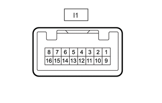
Disconnect the I1 cooler control switch assembly connector.
Measure the voltage and resistance according to the value(s) in the table below.
| Terminal No.
(Symbol) |
Terminal Description | Condition | Specified Condition |
|---|---|---|---|
| I1-1 (ACC) - Body ground | Power source (ACC) | Ignition switch off | Below 1 V |
| Ignition switch ACC | 11 to 14 V | ||
| I1-9 (+B) - Body ground | Power source (IG) | Ignition switch off | 11 to 14 V |
| I1-10 (+IG) - Body ground | Power source (IG) | Ignition switch off | Below 1 V |
| Ignition switch ON | 11 to 14 V | ||
| I1-16 (GND) - Body ground | Ground | Always | Below 1 Ω |
Reconnect the I1 cooler control switch assembly connector.
Check for pulse according to the value(s) in the table below.
| Terminal No.
(Symbol) |
Terminal Description | Condition | Specified Condition |
|---|---|---|---|
| I1-13 (RLIN) - Body ground | LIN communication line | Ignition switch ON | Ignition switch ON
(See waveform 1) |
Waveform 3:
| Item | Content |
|---|---|
| Terminal No. | I1-13 (RLIN) - Body ground |
| Tool Setting | 2 V/DIV., 20 μs./DIV. |
| Vehicle Condition | Ignition switch ON |
NO. 1 SEMICONDUCTOR POWER INTEGRATION ECU
Click herePower Source / Network>NETWORKING>CXPI COMMUNICATION SYSTEM>TERMINALS OF ECU