NETWORKING CXPI COMMUNICATION SYSTEM TERMINALS OF ECU
- NOTICE:
- ·
After turning the Ignition switch off, waiting time may be required before disconnecting the cable from the negative (-) auxiliary battery terminal.
Click hereGeneral>SETUP>WHEN DISCONNECTING OR RECONNECTING BATTERY TERMINAL>BEFORE DISCONNECTING BATTERY
·When disconnecting and reconnecting the auxiliary battery.
Click hereGeneral>SETUP>WHEN DISCONNECTING OR RECONNECTING BATTERY TERMINAL>WORK PROCEDURE
- HINT:
-
When disconnecting and reconnecting the auxiliary battery, there is an automatic learning function that completes learning when the respective system is used.
-
Click hereGeneral>SETUP>WHEN DISCONNECTING OR RECONNECTING BATTERY TERMINAL>AUTOMATIC LEARNING CHART
·Some parts must be initialized and set when replacing or removing and installing parts.
Click hereGeneral>SETUP>WHEN REPLACING OR REMOVING/INSTALLING PARTS>WORK PROCEDURE
CHECK DRIVER SIDE JUNCTION BLOCK ASSEMBLY AND MAIN BODY ECU (MULTIPLEX NETWORK BODY ECU)
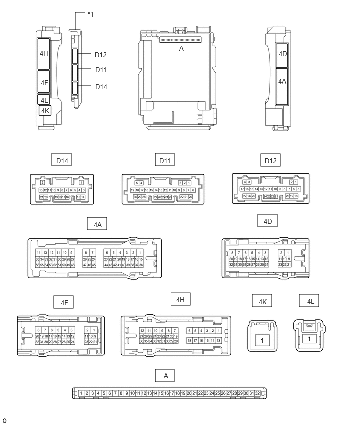
| *1 | Main Body ECU (Multiplex Network Body ECU) | - | - |
Remove the main body ECU (multiplex network body ECU).
Click herePower Source / Network>POWER DISTRIBUTION>MAIN BODY ECU>REMOVAL
Connect the main body ECU (multiplex network body ECU) connectors.
Measure the voltage and resistance according to the value(s) in the table below.
| Tester Connection | Terminal Description | Condition | Specified Condition |
|---|---|---|---|
| A-11 (GND1) - Body ground | Ground | Always | Below 1 Ω |
| A-31 (BECU) - Body ground | Battery power supply | Ignition switch off | 11 to 14 V |
| A-30 (ACC) - Body ground | ACC power supply | Ignition switch ACC | 11 to 14 V |
| Ignition switch off | Below 1 V | ||
| A-32 (IG) - Body ground | IG power supply | Ignition switch ON | 11 to 14 V |
| Ignition switch off | Below 1 V |
Install the main body ECU (multiplex network body ECU).
Click herePower Source / Network>POWER DISTRIBUTION>MAIN BODY ECU>INSTALLATION
Check for pulses according to the value(s) in the table below.
| Terminal No. (Symbol) | Terminal Description | Condition | Specified Condition |
|---|---|---|---|
| D14-5 (CXP1) - Body ground | CXPI communication line | Ignition switch ON | Pulse generation |
| D12-11 (CXP2) - Body ground | CXPI communication line | Ignition switch ON | Pulse generation |
NO. 1 SEMICONDUCTOR POWER INTEGRATION ECU (w/ PTC Heater)

| *a | Component without harness connected
(No. 1 Semiconductor Power Integration ECU) |
- | - |
Measure the voltage and resistance according to the value(s) in the table below.
| Terminal No. (Symbol) | Terminal Description | Condition | Specified Condition |
|---|---|---|---|
| A59-1 (+B) - Body ground | Battery power supply | Ignition switch off | 8 to 14 V |
| D123-9 (IG) - Body ground | Ignition power supply | Ignition switch off | Below 1.5 V |
| Ignition switch ON | 8 to 14 V | ||
| D123-13 (GND1) - Body ground | Ground | Always | Below 1 Ω |
Check for pulses according to the value(s) in the table below.
| Terminal No. (Symbol) | Terminal Description | Condition | Specified Condition |
|---|---|---|---|
| D123-7 (CXPI) - Body ground | CXPI communication line | Ignition switch ON | Pulse generation |
NO. 2 SEMICONDUCTOR POWER INTEGRATION ECU

| *a | Component without harness connected
(No. 2 Semiconductor Power Integration ECU) |
- | - |
Measure the voltage and resistance according to the value(s) in the table below.
| Terminal No. (Symbol) | Terminal Description | Condition | Specified Condition |
|---|---|---|---|
| J5-1 (+B) - Body ground | Battery power supply | Ignition switch off | 8 to 14 V |
| G102-6 (GND2) - Body ground | Ground | Always | Below 1 Ω |
| G102-9 (IG) - Body ground | Ignition power supply | Ignition switch off | Below 1.5 V |
| Ignition switch ON | 8 to 14 V | ||
| G102-13 (GND1) - Body ground | Ground | Always | Below 1 Ω |
| G102-14 (ACC) - Body ground | ACC stop lights operation signal input | Ignition switch off | 6 V or higher |
| Ignition switch ACC | Below 1.5 V |
Check for pulses according to the value(s) in the table below.
| Terminal No. (Symbol) | Terminal Description | Condition | Specified Condition |
|---|---|---|---|
| G102-7 (CXPI) - Body ground | CXPI communication line | Ignition switch ON | Pulse generation |
ROOM LIGHT CONTROL RELAY (FOR FRONT SIDE)(w/ Door Trim Illumination)
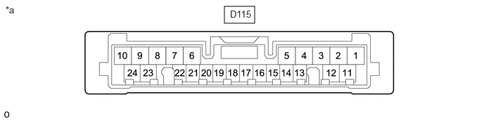
| *a | Component without harness connected
(Room Light Control Relay [for Front Side]) |
- | - |
Measure the voltage and resistance according to the value(s) in the table below.
| Terminal No. (Symbol) | Terminal Description | Condition | Specified Condition |
|---|---|---|---|
| D115-9 (E) - Body ground | Ground | Always | Below 1 Ω |
| D115-14 (ILA4) - Body ground | Battery power supply | Ignition switch off | 11 to 14 V |
Check for pulses according to the value(s) in the table below.
| Terminal No. (Symbol) | Terminal Description | Condition | Specified Condition |
|---|---|---|---|
| D115-10 (CXPI) - Body ground | CXPI communication line | Ignition switch ON | Pulse generation |
ROOM LIGHT CONTROL RELAY (FOR REAR SIDE)(w/ Door Trim Illumination)
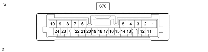
| *a | Component without harness connected
(Room Light Control Relay [for Rear Side]) |
- | - |
Measure the voltage and resistance according to the value(s) in the table below.
| Terminal No. (Symbol) | Terminal Description | Condition | Specified Condition |
|---|---|---|---|
| G76-7 (BU+) - Body ground | Battery power supply | Ignition switch off | 11 to 14 V |
| G76-9 (BU-) - Body ground | Ground | Always | Below 1 Ω |
Check for pulses according to the value(s) in the table below.
| Terminal No. (Symbol) | Terminal Description | Condition | Specified Condition |
|---|---|---|---|
| G76-10 (CXPI) - Body ground | CXPI communication line | Ignition switch ON | Pulse generation |