FUEL FUEL SYSTEM ON-VEHICLE INSPECTION
PROCEDURE

 1.INSPECT HYDROGEN TANK ASSEMBLY FOR HYDROGEN GAS LEAK
Pre-procedure1
Remove the rear No.4 floor board sub-assembly.
Remove the rear No.3 floor board sub-assembly.
Remove the No. 2 floor board sub-assembly.
Remove the No. 1 floor board sub-assembly.
Remove the rear floor side member cover LH.
Remove the rear floor side member cover RH.
Remove the No. 1 floor under cover.
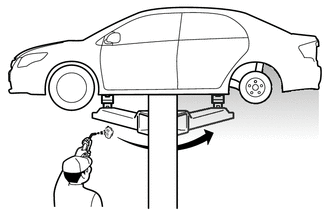
Blow compressed air around the front compartment room and underside of the vehicle.
- HINT:
-
To enable accurate detection of hydrogen gas leaks from the piping, blow compressed air from the front of the vehicle towards the rear.
If there are water droplets, etc. adhering to any of the measurement locations, wipe them away before performing the procedures.
- NOTICE:
-
If measurements are performed while water droplets, etc. are adhered, the hydrogen gas detector may be damaged.
Procedure1
Using SST and a hydrogen gas detector, measure each of the measurement locations for approximately 10 continuous seconds per location.
- SST
- 09401-62020
- NOTICE:
- ·
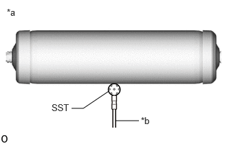 1.75,1.833 2.104,1.833 false 1.083,1.646 1.26,1.646 1.26,1.646 1.646,1.385 false 2.135,1.75 2.448,1.906 0.313,0.156 10 false *b 0.781,1.552 1.24,1.75 0.458,0.198 10 false SST 0.104,0.104 0.375,0.313 0.271,0.208 10 false *a
*a Hydrogen Gas Detector Contact Location *b Hydrogen Gas Detector
To perform the measurement, hold the tip of the hydrogen gas detector as shown in the illustration.
·Hold the tip in light contact with the location so that the tip does not deform.
- HINT:
-
Immediately after the measurement starts, the measured value may be unstable.
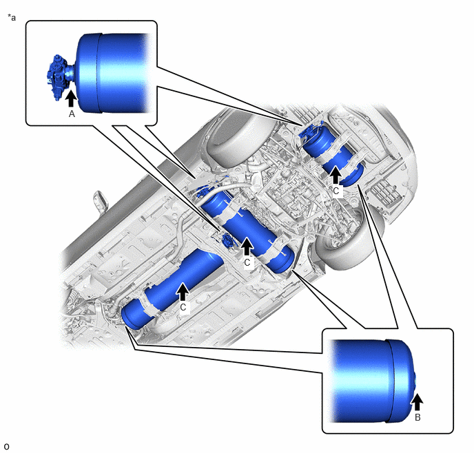
| *a | Measurement Locations | - | - |
| Illustration Item | Measurement Location | Measurement Method | Specified Value |
|---|---|---|---|
| A | Boss Valve Side of Hydrogen Tank Assembly | Measure the area near the boss or center of Hydrogen Tank Assembly. | Less than 500 ppm |
| B | Boss End Side of Hydrogen Tank Assembly | ||
| C | Center of Hydrogen Tank Assembly
(1 location in center of hydrogen tank assembly from underside of vehicle) |
If the specification is not met, replace the hydrogen tank assembly with a new one.
Post-procedure1
Install the No. 1 floor under cover.
Install the rear floor side member cover RH.
Install the rear floor side member cover LH.
Install the No. 1 floor board sub-assembly.
Install the No. 2 floor board sub-assembly.
Install the rear No.3 floor board sub-assembly.
Install the rear No.4 floor board sub-assembly.
2.INSPECT HYDROGEN TANK ASSEMBLY
Pre-procedure1
Remove the rear No.4 floor board sub-assembly.
Remove the rear No.3 floor board sub-assembly.
Remove the No. 2 floor board sub-assembly.
Remove the No. 1 floor board sub-assembly.
Remove the rear floor side member cover LH.
Remove the rear floor side member cover RH.
Remove the No. 1 floor under cover.
Procedure1
Check that the hydrogen tank assembly is not damaged.
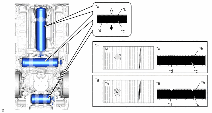
| *a | Hydrogen Tank Assembly Cutaway View | *b | GFRP (Glass Fiber Reinforced Plastic) Layer |
| *c | CFRP (Carbon Fiber Reinforced Plastic) Layer (Black) | *d | Resin Liner |
| *e | Pass | *f | CFRP (Carbon Fiber Reinforced Plastic) Layer (Black) is not exposed |
| *g | Reject | *h | CFRP (Carbon Fiber Reinforced Plastic) Layer (Black) is exposed |

|
Hydrogen Tank Assembly Inner Side | 
|
Hydrogen Tank Assembly Outer Side |
- OK:
The CFRP (Carbon Fiber Reinforced Plastic) Layer (Black) must not be exposed.
- HINT:
-
If the specification is not met, replace the hydrogen tank assembly with a new one.
Post-procedure1
Install the No. 1 floor under cover.
Install the rear floor side member cover RH.
Install the rear floor side member cover LH.
Install the No. 1 floor board sub-assembly.
Install the No. 2 floor board sub-assembly.
Install the rear No.3 floor board sub-assembly.
Install the rear No.4 floor board sub-assembly.
3.INSPECT FOR HYDROGEN GAS LEAK
- NOTICE:
-
Perform the hydrogen gas leak inspection when the fuel remaining warning light is not illuminated.
Pre-procedure1
Remove the rear No.4 floor board sub-assembly.
Remove the rear No.3 floor board sub-assembly.
Remove the No. 2 floor board sub-assembly.
Remove the rear floor side member cover LH.
Remove the No. 1 floor under cover.
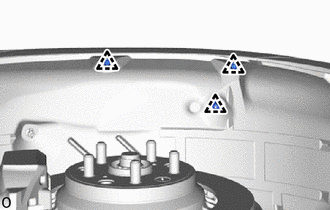
Detach the 3 clips and peel back the rear wheel house liner LH.
Blow compressed air around the front compartment room and underside of the vehicle.
- HINT:
-
To enable accurate detection of hydrogen gas leaks from the piping, blow compressed air from the front of the vehicle towards the rear.
If there are water droplets, etc. adhering to any of the measurement locations, wipe them away before performing the procedures.
- NOTICE:
-
If measurements are performed while water droplets, etc. are adhered, the hydrogen gas detector may be damaged.
Procedure1
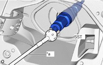
| *a | Hydrogen Leak Detector |

|
Contact Area for Hydrogen Leak Detector |
Using SST and a hydrogen gas detector, measure each of the measurement locations for approximately 10 continuous seconds per location.
- SST
- 09401-62020
- NOTICE:
- ·
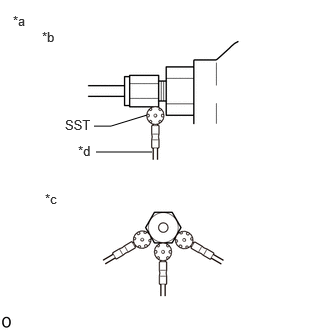 1.531,1.198 1.156,1.313 1.156,1.313 0.979,1.313 false 1,1.583 1.583,1.583 false 0.438,0.302 0.75,0.458 0.313,0.156 10 false *b 0.469,1.99 0.781,2.146 0.313,0.156 10 false *c 0.677,1.219 0.99,1.375 0.313,0.156 10 false SST 0.813,1.49 1,1.646 0.188,0.156 10 false *d 0.135,0.135 0.448,0.292 0.313,0.156 10 false *a
*a Hydrogen Gas Detector Contact Location and Direction *b Side View *c Cutaway View *d Hydrogen Gas Detector
To perform the measurement, hold the tip of the hydrogen gas detector as shown in the illustration (*c), in contact with a single location from any one of the directions shown.
·Hold the tip in light contact with the location so that the tip does not deform.
- HINT:
- ·
Immediately after the measurement starts, the measured value may be unstable.
·If the measured value is outside of the specification, remove the hydrogen tank unit from the vehicle and replace the leaking component with a new one.
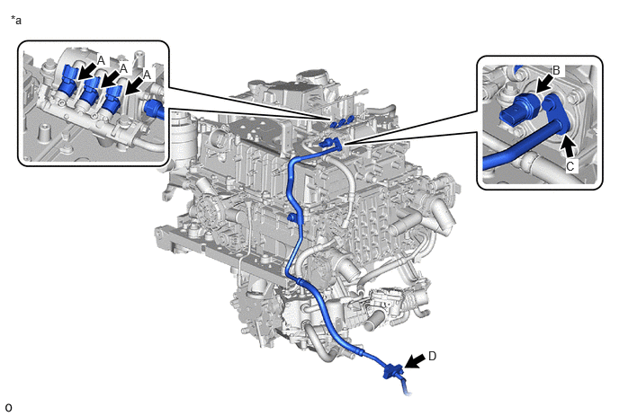
| *a | Measurement Locations | - | - |
| Illustration Item | Measurement Location | Measurement Method | Specified Value |
|---|---|---|---|
| A | Connection between Hydrogen Supply Primary Pipe Sub-assembly x Fuel Injector Assembly | Measure the area near the piping, connecting portion, or sensor connecting portion. | Less than 500 ppm |
| B | Connection between Hydrogen Supply Primary Pressure Sensor x Hydrogen Supply Secondary Pipe Sub-assembly | ||
| C | Connection between No. 1 Hydrogen Supply Tube x Hydrogen Supply Secondary Pipe Sub-assembly | ||
| D | Connection between No. 1 Hydrogen Supply Tube x No. 2 Hydrogen Supply Tube |
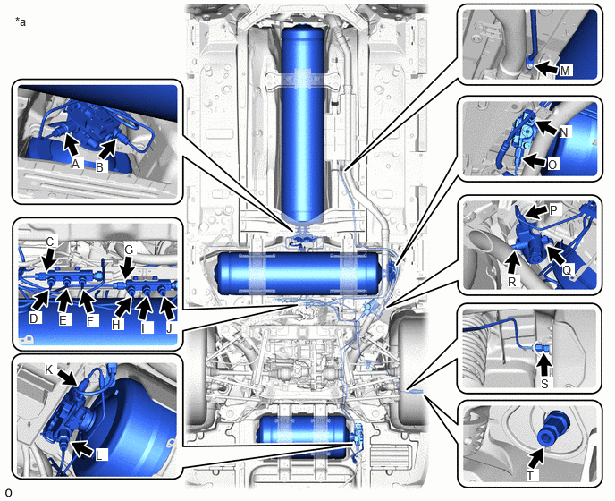
| *a | Measurement Location | - | - |
| Illustration Item | Measurement Location | Measurement Method | Specified Value |
|---|---|---|---|
| A | Connection between No. 2 Hydrogen Tank Tube and No. 1 Hydrogen Tank Assembly | Measure the area near the piping, connecting portion, or sensor connecting portion. | Less than 500 ppm |
| B | Connection between No. 5 Hydrogen Tank Tube and No. 1 Hydrogen Tank Assembly | ||
| C | Connection between No. 3 Hydrogen Tank Tube and Hydrogen Tank Tube Joint Assembly (for Inlet Side) | ||
| D | Connection between No. 1 Hydrogen Tank Tube and Hydrogen Tank Tube Joint Assembly (for Inlet Side) | ||
| E | Connection between No. 4 Hydrogen Tank Tube and Hydrogen Tank Tube Joint Assembly (for Inlet Side) | ||
| F | Connection between No. 2 Hydrogen Tank Tube and Hydrogen Tank Tube Joint Assembly (for Inlet Side) | ||
| G | Connection between No. 6 Hydrogen Tank Tube and Hydrogen Tank Tube Joint Assembly (for Outlet Side) | ||
| H | Connection between No. 8 Hydrogen Tank Tube and Hydrogen Tank Tube Joint Assembly (for Outlet Side) | ||
| I | Connection between No. 7 Hydrogen Tank Tube and Hydrogen Tank Tube Joint Assembly (for Outlet Side) | ||
| J | Connection between No. 5 Hydrogen Tank Tube and Hydrogen Tank Tube Joint Assembly (for Outlet Side) | ||
| K | Connection between No. 7 Hydrogen Tank Tube and No. 3 Hydrogen Tank Assembly | ||
| L | Connection between No. 4 Hydrogen Tank Tube and No. 3 Hydrogen Tank Assembly | ||
| M | Connection between No. 2 Hydrogen Supply Tube Sub-assembly and No. 3 Hydrogen Supply Tube Sub-assembly | ||
| N | Connection between No. 6 Hydrogen Tank Tube and No. 2 Hydrogen Tank Assembly | ||
| O | Connection between No. 3 Hydrogen Tank Tube and No. 2 Hydrogen Tank Assembly | ||
| P | Connection between No. 8 Hydrogen Tank Tube and Hydrogen Supply Regulator | ||
| Q | Medium Pressure Port of Hydrogen Supply Regulator
*1 |
||
| R | Connection between No. 3 Hydrogen Supply Tube Sub-assembly and Hydrogen Supply Regulator | ||
| S | Connection between No. 1 Hydrogen Tank Tube and Hydrogen Inlet Receptacle
*2 |
||
| T | Filling Port of Hydrogen Inlet Receptacle | Perform measurement with the tip of the hydrogen leak detector in direct contact with the filling port.
*4, *5 |
1000 ppm or less |
*1: If the value is not as specified, replace the O-ring of the medium pressure port.
*2: Measure from underneath the vehicle, with the rear wheel house liner LH peeled back.
*3: Because there is a possibility of erroneously detecting hydrogen that has accumulated near the filling port, open the hydrogen inlet receptacle cap and wait for at least 3 minutes before performing the measurement.
| *a | Hydrogen Leak Detector |
|
|
Contact Area for Hydrogen Leak Detector |
*4: When performing leak inspection of the hydrogen inlet receptacle assembly, hold the tip of the hydrogen leak detector in light contact with the area shown in the illustration.
*5: To prevent damage to the O-ring, do not insert the tip of the hydrogen leak detector into the filling port of the hydrogen inlet receptacle assembly.
Post-procedure1
Connect the hydrogen inlet receptacle cap and closed fuel lid.
Attach the 3 clips and install the rear wheel house liner LH.
Install the No. 1 floor under cover.
Install the rear floor side member cover LH.
Install the No. 2 floor board sub-assembly.
Install the rear No.3 floor board sub-assembly.
Install the rear No.4 floor board sub-assembly.
4. FIRST LEAK CHECK
- HINT:
- ·
When replacing or removing and installing any high pressure hydrogen system component (hydrogen inlet receptacle assembly, hydrogen tank tube joint assembly, hydrogen tank assembly, hydrogen supply regulator, or hydrogen tank tube), perform the primary leak inspection.
·The primary leak inspection is performed using nitrogen gas.
·When performing the primary leak inspection, remove the floor covers and rear wheel house liner so that the high pressure and medium pressure hydrogen system components and high pressure and medium pressure hydrogen system pipes are visible during inspection.
- CAUTION:
-
- ·
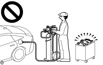
When performing the primary leak inspection, do not perform procedures without wearing protective glasses and gloves.
·High pressure nitrogen gas could cause a serious accident.
- NOTICE:
-
After performing the primary leak inspection and confirming that there are no leaks, perform secondary leak inspection.
Pre-procedure1
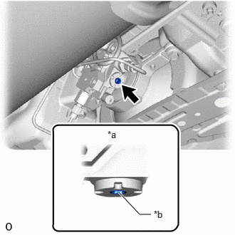
| *a | Manual Valve Closed |
| *b | Adjustment Bolt |
Using an 8 mm socket hexagon wrench, apply the specified tightening torque to the adjustment bolt to make sure the manual valve of the No. 1 hydrogen tank assembly is closed.
- Torque:
- 25 N*m (255 kgf*cm, 18 ft.*lbf)
- NOTICE:
- ·
The manual valve shuts off the pressure from the hydrogen tank assembly, so be careful not to damage the hexagonal portion.
·If the hexagonal portion has been damaged, the No. 1 hydrogen tank assembly must be replaced.
·To prevent nitrogen gas from flowing into the hydrogen tank assembly, do not open the manual valve until after the primary leak inspection is completed.
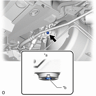
| *a | Manual Valve Closed |
| *b | Adjustment Bolt |
Using an 8 mm socket hexagon wrench, apply the specified tightening torque to the adjustment bolt to make sure the manual valve of the No. 2 hydrogen tank assembly is closed.
- Torque:
- 25 N*m (255 kgf*cm, 18 ft.*lbf)
- NOTICE:
- ·
The manual valve shuts off the pressure from the hydrogen tank assembly, so be careful not to damage the hexagonal portion.
·If the hexagonal portion has been damaged, the No. 2 hydrogen tank assembly must be replaced.
·To prevent nitrogen gas from flowing into the hydrogen tank assembly, do not open the manual valve until after the primary leak inspection is completed.
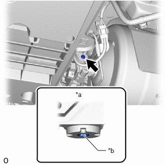
| *a | Manual Valve Closed |
| *b | Adjustment Bolt |
Using an 8 mm socket hexagon wrench, apply the specified tightening torque to the adjustment bolt to make sure the manual valve of the No. 1 hydrogen tank assembly is closed.
- Torque:
- 25 N*m (255 kgf*cm, 18 ft.*lbf)
- NOTICE:
- ·
The manual valve shuts off the pressure from the hydrogen tank assembly, so be careful not to damage the hexagonal portion.
·If the hexagonal portion has been damaged, the No. 1 hydrogen tank assembly must be replaced.
·To prevent nitrogen gas from flowing into the hydrogen tank assembly, do not open the manual valve until after the primary leak inspection is completed.
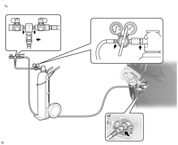
Prepare SST (10 MPa leak inspection tool).
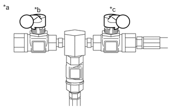
| *a | SST (Port Assembly) |
| *b | Discharge Valve Closed Condition |
| *c | Injection Valve Closed Condition |
Check that the injection valve and discharge valve of SST (port assembly) are closed.
- SST
- 09402-62010 (09402-06020)
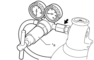
| *a | SST (Regulator Assembly) |
Connect SST (regulator assembly) to a nitrogen cylinder.
- SST
- 09402-62010 (09402-06010)
- NOTICE:
- ·
Wrap the threaded portion with seal tape.
·Securely tighten so that nitrogen gas will not leak out.
Connect the nitrogen cylinder and SST (10 MPa leak inspection tool) to the hydrogen inlet receptacle.
- SST
- 09402-62010 (09402-06010, 09402-06020)
- NOTICE:
- ·
Leave the nitrogen regulator valve closed.
·The internal volume from the cylinder to the nozzle should be 130 cc or less.
·The smallest marking of the pressure system should be 0.2 MPa (2.0 kgf/cm2, 29 psi) or less.
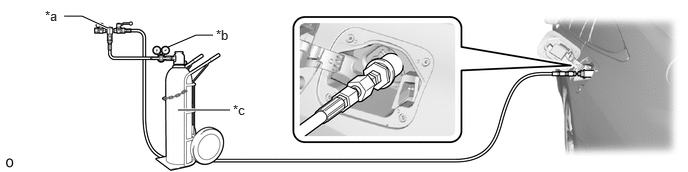
| *a | SST (Port Assembly) | *b | SST (Regulator Assembly) |
| *c | Nitrogen Cylinder | - | - |
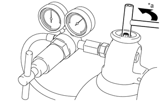
| *a | Open the Nitrogen Cylinder Valve |
Slowly open the nitrogen cylinder valve.
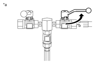
| *a | SST (Port Assembly) |
| *b | Slowly Open |
Slowly open the injection valve of SST (port assembly).
- SST
- 09402-62010 (09402-06020)
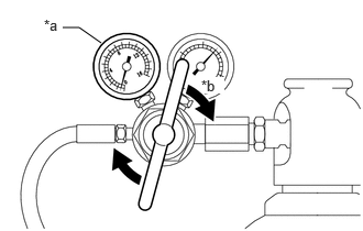
| *a | SST (Regulator Assembly) |
| *b | Open the Nitrogen Cylinder Valve |
Slowly rotate the handle of SST (regulator assembly) in the clockwise direction to open the valve, and let the pressure rise to 10 MPa (102.0 kgf/cm2, 1450 psi).
- SST
- 09402-62010 (09402-06010)
- NOTICE:
- ·
Raise the pressure to 10 MPa (102.0 kgf/cm2, 1450 psi) over a period of 5 to 20 seconds.
·If there is a hissing sound of nitrogen gas leaking out when the SST (regulator assembly) valve is opened, close the SST (regulator assembly) valve, and after determining the location of the leak, replace the leaking component with a new one.
·Even when it seems like the leaking sound is only coming from one location, it may be drowning out leaking sounds from other locations, so make sure to perform leakage point identification for all connecting portions.
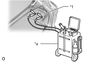
| *1 | Auxiliary Battery |
| *a | Battery Charger |
Connect a battery charger to the auxiliary battery, and put the auxiliary battery into a charging state.
- HINT:
-
This is done to prevent the auxiliary battery from becoming discharged, as the tank shut valve of the hydrogen tank assembly will be forced to operate for 30 minutes.
Using the GTS, enter the following menus: Body Electrical / Power Source Control / Utility / Auto Power OFF Cancel
- Body Electrical > Power Source Control > Utility
-
Tester Display Auto Power OFF Cancel - 50005 223 4148
Open the tank shut valves of the No. 1 hydrogen tank assembly, No. 2 hydrogen tank assembly and No. 3 hydrogen tank assembly.
- NOTICE:
- ·
If the Data List item "Medium-range Hydrogen Pressure (gauge)" decreases to below 0.7 MPa (7.1 kgf/cm2, 102 psi) the tank shut valves of the No. 1 hydrogen tank assembly, No. 2 hydrogen tank assembly and No. 3 hydrogen tank assembly will forcibly close.
·If there is a hissing sound of nitrogen gas leaking out when the tank shut valves are opened, close both tank shut valves, and after determining the location of the leak, replace the leaking component with a new one.
·Even when it seems like the leaking sound is only coming from one location, it may be drowning out leaking sounds from other locations, so make sure to perform leakage point identification for all connecting portions.
If the tank shut valves of the No. 1 hydrogen tank assembly, No. 2 hydrogen tank assembly and No. 3 hydrogen tank assembly do not open, open the tank shut valves again.
When the tank shut valve has been opened, if the pressure has gone below 10 MPa (102.0 kgf/cm2, 1450 psi), increase the pressure to 10 MPa (102.0 kgf/cm2, 1450 psi).
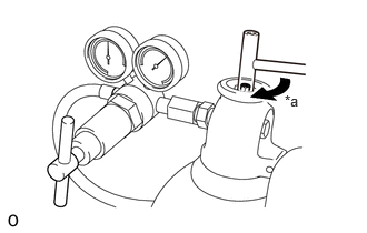
| *a | Close the Nitrogen Cylinder Valve |
Close the nitrogen cylinder valve.
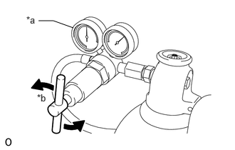
| *a | SST (Regulator Assembly) |
| *b | Close the SST (Regulator Assembly) Valve |
Rotate the handle of SST (regulator assembly) in the counterclockwise direction to close the valve.
- SST
- 09402-62010 (09402-06010)
After closing the nitrogen cylinder valve and the SST (regulator assembly) valve, wait for 10 minutes to allow the pressure in the piping to stabilize.
- HINT:
-
When nitrogen has just been filled, the temperature inside the piping is increased, causing pressure to increase. Afterwards, when the temperature in the piping decreases, the pressure decreases. For this reason, pressure is not stable immediately after nitrogen filling.
Procedure1
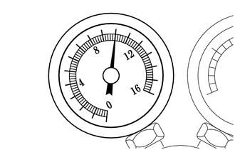
After checking that the pressure gauge has stabilized, wait an additional 30 minutes, and then check the pressure gauge.
- OK:
Pressure decrease is 0.2 MPa (2.0 kgf/cm2, 29 psi) or less
When the pressure decrease is 0.2 MPa (2.0 kgf/cm2, 29 psi) or less:
Go to "When pressure decrease is 0.2 MPa (2.0 kgf/cm2, 29 psi) or less"
When the pressure decrease is more than 0.2 MPa (2.0 kgf/cm2, 29 psi):
Go to "When pressure decrease is more than 0.2 MPa (2.0 kgf/cm2, 29 psi)
Post-procedure1
When pressure decrease is 0.2 MPa (2.0 kgf/cm2, 29 psi) or less:
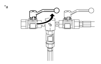
| *a | SST (Port Assembly) |
| *b | Open the Discharge Valve of SST (Port Assembly) |
Slowly open the discharge valve of SST (port assembly) to depressurize the nitrogen gas.
- SST
- 09402-62010 (09402-06020)
- NOTICE:
-
Keep your hands and face away from the discharge port.
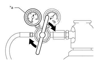
| *a | SST (Regulator Assembly) |
| *b | Open the SST (Regulator Assembly) Valve |
Slowly rotate the handle of SST (regulator assembly) a small amount in the clockwise direction to open the valve.
- SST
- 09402-62010 (09402-06010)
- HINT:
-
This is done to reduce the pressure of the nitrogen gas between the nitrogen cylinder and SST (regulator assembly).
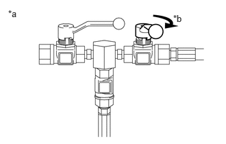
| *a | SST (Port Assembly) |
| *b | Close the Injection Valve of SST (Port Assembly) |
Close the injection valve of SST (port assembly).
- SST
- 09402-62010 (09402-06020)
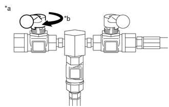
| *a | SST (Port Assembly) |
| *b | Close the Discharge Valve of SST (Port Assembly) |
Close the discharge valve of SST (port assembly).
- SST
- 09402-62010 (09402-06020)
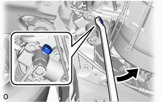
Slowly loosen the No. 1 hydrogen supply regulator plug until the hissing sound of gas escaping can be heard, then stop loosening the No. 1 hydrogen supply regulator plug and wait for the sound to stop. Repeat this procedure multiple times until the sound stops occurring, in order to depressurize the nitrogen gas from the medium pressure leak check port of the hydrogen supply regulator.
- NOTICE:
-
When depressurizing the nitrogen gas, only loosen the No. 1 hydrogen supply regulator plug. Do not remove it.
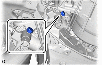
Remove the No. 1 hydrogen supply regulator plug from the hydrogen supply regulator.
- NOTICE:
-
When frost has formed on the hydrogen tank assembly or piping, water droplets may be formed when the frost begins to melt. If water droplets enter the tank or piping, it could result in blockage of the hydrogen piping, so do not allow water droplets to enter the tank or piping.
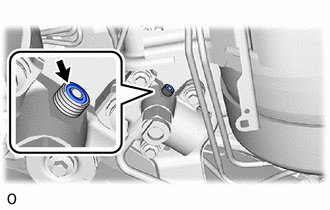
Remove the O-ring from the hydrogen supply regulator.
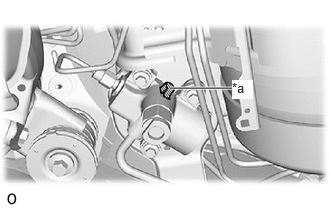
| *a | Protective Tape |
To prevent damage to the seal portions and threaded portions, and to prevent foreign matter such as dust or metal fragments from entering the openings, cover the seal portions, threaded portions, and openings of the hydrogen supply regulator with protective tape.
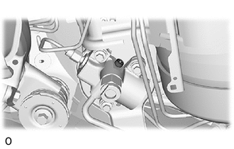
To prevent damage to the seal portions and threaded portions, and to prevent foreign matter such as dust or metal fragments from entering the openings, do not remove the protective tape covering the seal portions, threaded portions, and openings of the hydrogen supply regulator until immediately before performing work.
- NOTICE:
-
When frost has formed on the hydrogen tank assembly or piping, water droplets may be formed when the frost begins to melt. If water droplets enter the tank or piping, it could result in blockage of the hydrogen piping, so do not allow water droplets to enter the tank or piping.
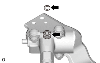
Apply TOYOTA Genuine FC Grease to a new O-ring and to the threaded portion of the hydrogen supply regulator.
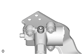
Install the O-ring to the hydrogen supply regulator.
- NOTICE:
-
During installation, make sure not to damage the O-ring.
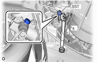
| *a | Torque Wrench Fulcrum Length |
Using SST install the No. 1 hydrogen supply regulator plug to the hydrogen supply regulator.
- SST
- 09922-10240
- Torque:
- Specified tightening torque:
9.0 N*m (92 kgf*cm, 80 in.*lbf)
- HINT:
- ·
Calculate the torque wrench reading when changing the fulcrum length of the torque wrench.
Click hereGeneral>INTRODUCTION>REPAIR INSTRUCTION>PRECAUTION
·When using SST (fulcrum length of 40 mm (1.57 in.)) + torque wrench (fulcrum length of 162 mm (6.38 in.)): 7.2 N*m (73 kgf*cm, 64 in.*lbf)
Close the tank shut valve of the No. 1 hydrogen tank assembly, No. 2 hydrogen tank assembly and No. 3 hydrogen tank assembly.
Disconnect the nitrogen cylinder and SST (10 MPa leak inspection tool) from the hydrogen inlet receptacle.
- SST
- 09402-62010 (09402-06010, 09402-06020)
| *a | SST (Port Assembly) | *b | SST (Regulator Assembly) |
| *c | Nitrogen Cylinder | - | - |
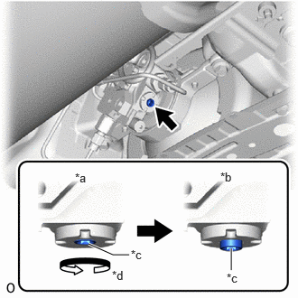
| *a | Manual Valve Closed |
| *b | Manual Valve Open |
| *c | Adjustment Bolt |
| *d | Counterclockwise |
Using an 8 mm socket hexagon wrench, rotate the adjustment bolt counterclockwise, and open the No. 1 hydrogen tank assembly manual valve.
- NOTICE:
- ·
The manual valve shuts off the pressure from the hydrogen tank assembly, so be careful not to damage the hexagonal portion.
·If the hexagonal portion is damaged, it will be impossible to operate the adjustment bolt.
·Do not rotate the adjustment bolt more than 4 rotations.
·Rotating the adjustment bolt more than 4 rotations could damage the manual valve.
·If the manual valve is damaged, it will be necessary to replace the No. 1 hydrogen tank assembly.
·Before opening the manual valve, check that the nitrogen gas contained in the hydrogen piping has been depressurized.
- HINT:
-
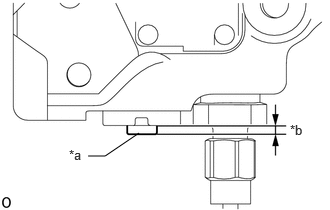 0.917,1.625 1.094,1.625 1.094,1.625 1.448,1.385 false 0.719,1.531 1.031,1.688 0.313,0.156 10 false *a 3.021,1.271 3.25,1.427 0.229,0.156 10 false *b
*a Adjustment Bolt *b Protrusion
-
When the manual valve is opened, the protrusion of the adjustment bolt is 3.5 mm (0.138 in.) or less.
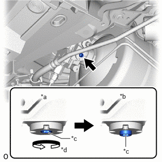
| *a | Manual Valve Closed |
| *b | Manual Valve Open |
| *c | Adjustment Bolt |
| *d | Counterclockwise |
Using an 8 mm socket hexagon wrench, rotate the adjustment bolt counterclockwise, and open the No. 2 hydrogen tank assembly manual valve.
- NOTICE:
- ·
The manual valve shuts off the pressure from the hydrogen tank assembly, so be careful not to damage the hexagonal portion.
·If the hexagonal portion is damaged, it will be impossible to operate the adjustment bolt.
·Do not rotate the adjustment bolt more than 4 rotations.
·Rotating the adjustment bolt more than 4 rotations could damage the manual valve.
·If the manual valve is damaged, it will be necessary to replace the No. 2 hydrogen tank assembly.
·Before opening the manual valve, check that the nitrogen gas contained in the hydrogen piping has been depressurized.
- HINT:
-
0.917,1.625 1.094,1.625 1.094,1.625 1.448,1.385 false 0.719,1.531 1.031,1.688 0.313,0.156 10 false *a 3.021,1.271 3.25,1.427 0.229,0.156 10 false *b
*a Adjustment Bolt *b Protrusion
-
When the manual valve is opened, the protrusion of the adjustment bolt is 3.5 mm (0.138 in.) or less.
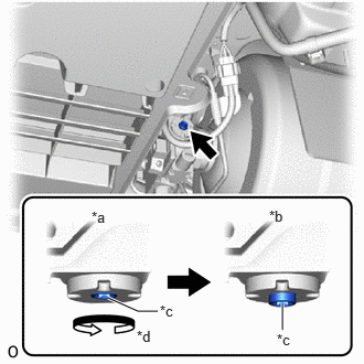
| *a | Manual Valve Closed |
| *b | Manual Valve Open |
| *c | Adjustment Bolt |
| *d | Counterclockwise |
Using an 8 mm socket hexagon wrench, rotate the adjustment bolt counterclockwise, and open the No. 3 hydrogen tank assembly manual valve.
- NOTICE:
- ·
The manual valve shuts off the pressure from the hydrogen tank assembly, so be careful not to damage the hexagonal portion.
·If the hexagonal portion is damaged, it will be impossible to operate the adjustment bolt.
·Do not rotate the adjustment bolt more than 4 rotations.
·Rotating the adjustment bolt more than 4 rotations could damage the manual valve.
·If the manual valve is damaged, it will be necessary to replace the No. 3 hydrogen tank assembly.
·Before opening the manual valve, check that the nitrogen gas contained in the hydrogen piping has been depressurized.
- HINT:
-
0.917,1.625 1.094,1.625 1.094,1.625 1.448,1.385 false 0.719,1.531 1.031,1.688 0.313,0.156 10 false *a 3.021,1.271 3.25,1.427 0.229,0.156 10 false *b
*a Adjustment Bolt *b Protrusion
-
When the manual valve is opened, the protrusion of the adjustment bolt is 3.5 mm (0.138 in.) or less.
When pressure decrease is more than 0.2 MPa (2.0 kgf/cm2, 29 psi):
Using soapy water, check the connection points to determine the locations of the leaks.
- HINT:
-
If the soapy water on the part connection points is difficult to see, use a mirror and a light.
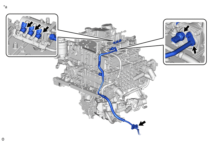
| *a | FC Stack-side Leak Check Locations | - | - |
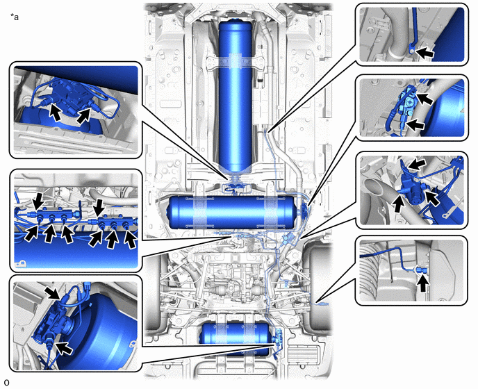
| *a | Hydrogen Tank-side Leak Check Locations | - | - |
| *a | Nitrogen Regulator-side Leak Check Locations | - | - |
| *a | SST (Port Assembly) |
| *b | Open the Discharge Valve of SST (Port Assembly) |
Slowly open the discharge valve of SST (port assembly) to depressurize the nitrogen gas.
- SST
- 09402-62010 (09402-06020)
- NOTICE:
-
Keep your hands and face away from the discharge port.
| *a | SST (Regulator Assembly) |
| *b | Open the SST (Regulator Assembly) Valve |
Slowly rotate the handle of SST (regulator assembly) a small amount in the clockwise direction to open the valve.
- SST
- 09402-62010 (09402-06010)
- HINT:
-
This is done to reduce the pressure of the nitrogen gas between the nitrogen cylinder and SST (regulator assembly).
| *a | SST (Port Assembly) |
| *b | Close the Injection Valve of SST (Port Assembly) |
Close the injection valve of SST (port assembly).
- SST
- 09402-62010 (09402-06020)
| *a | SST (Port Assembly) |
| *b | Close the Discharge Valve of SST (Port Assembly) |
Close the discharge valve of SST (port assembly).
- SST
- 09402-62010 (09402-06020)
Slowly loosen the No. 1 hydrogen supply regulator plug until the hissing sound of gas escaping can be heard, then stop loosening the No. 1 hydrogen supply regulator plug and wait for the sound to stop. Repeat this procedure multiple times until the sound stops occurring, in order to depressurize the nitrogen gas from the medium pressure leak check port of the hydrogen supply regulator.
- NOTICE:
-
When depressurizing the nitrogen gas, only loosen the No. 1 hydrogen supply regulator plug. Do not remove it.
Remove the No. 1 hydrogen supply regulator plug from the hydrogen supply regulator.
- NOTICE:
-
When frost has formed on the hydrogen tank assembly or piping, water droplets may be formed when the frost begins to melt. If water droplets enter the tank or piping, it could result in blockage of the hydrogen piping, so do not allow water droplets to enter the tank or piping.
Remove the O-ring from the hydrogen supply regulator.
| *a | Protective Tape |
To prevent damage to the seal portions and threaded portions, and to prevent foreign matter such as dust or metal fragments from entering the openings, cover the seal portions, threaded portions, and openings of the hydrogen supply regulator with protective tape.
To prevent damage to the seal portions and threaded portions, and to prevent foreign matter such as dust or metal fragments from entering the openings, do not remove the protective tape covering the seal portions, threaded portions, and openings of the hydrogen supply regulator until immediately before performing work.
- NOTICE:
-
When frost has formed on the hydrogen tank assembly or piping, water droplets may be formed when the frost begins to melt. If water droplets enter the tank or piping, it could result in blockage of the hydrogen piping, so do not allow water droplets to enter the tank or piping.
Apply TOYOTA Genuine FC Grease to a new O-ring and to the threaded portion of the hydrogen supply regulator.
Install the O-ring to the hydrogen supply regulator.
- NOTICE:
-
During installation, make sure not to damage the O-ring.
| *a | Torque Wrench Fulcrum Length |
Using SST install the No. 1 hydrogen supply regulator plug to the hydrogen supply regulator.
- SST
- 09922-10240
- Torque:
- Specified tightening torque:
9.0 N*m (92 kgf*cm, 80 in.*lbf)
- HINT:
- ·
Calculate the torque wrench reading when changing the fulcrum length of the torque wrench.
Click hereGeneral>INTRODUCTION>REPAIR INSTRUCTION>PRECAUTION
·When using SST (fulcrum length of 40 mm (1.57 in.)) + torque wrench (fulcrum length of 162 mm (6.38 in.)): 7.2 N*m (73 kgf*cm, 64 in.*lbf)
Close the tank shut valve of the No. 1 hydrogen tank assembly, No. 2 hydrogen tank assembly and No. 3 hydrogen tank assembly.
Disconnect the nitrogen cylinder and SST (10 MPa leak inspection tool) from the hydrogen inlet receptacle.
- SST
- 09402-62010 (09402-06010, 09402-06020)
| *a | SST (Port Assembly) | *b | SST (Regulator Assembly) |
| *c | Nitrogen Cylinder | - | - |
After replacing the leaking component with a new one, perform primary leak inspection again.
5. SECOND LEAK CHECK
- NOTICE:
- ·
Secondary leak inspection is performed after primary leak inspection has found no leaks.
·When replacing or removing and installing any high pressure hydrogen system component (the hydrogen inlet receptacle assembly, hydrogen tank tube joint assembly, hydrogen tank assembly, hydrogen supply regulator, or hydrogen tank tube), transport the vehicle to a hydrogen station such as on a car transporter and fill the tanks completely with compressed hydrogen gas.
- HINT:
- ·
When replacing or removing and installing the high pressure hydrogen system components, and when removing and installing medium pressure and high-pressure hydrogen pipes, perform the secondary leak inspection.
·Hydrogen gas may stay near the hydrogen detector, detect hydrogen leaks, and output DTC. Perform the secondary leak inspection with the No. 3 FC exhaust pipe installed.
Pre-procedure1
When replacing or removing and installing high pressure hydrogen system components:
At the hydrogen station, fill the tanks completely with compressed hydrogen gas.
Blow compressed air around the front compartment room and underside of the vehicle.
- HINT:
-
To enable accurate detection of hydrogen gas leaks from the piping, blow compressed air from the front of the vehicle towards the rear.
If there are water droplets, etc. adhering to any of the measurement locations, wipe them away before performing the procedures.
- NOTICE:
-
If measurements are performed while water droplets, etc. are adhered, the hydrogen gas detector may be damaged.
Connect the GTS to the DLC3.
Turn the ignition switch on (IG).
Enter the following menus: Powertrain / EV / Utility / Leak Check
- Powertrain > EV > Utility
-
Tester Display Leak Check - 50005 397 4671
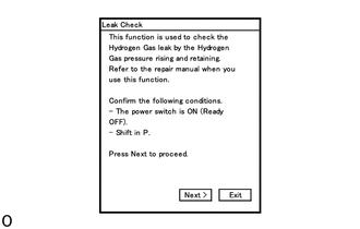
Following the display on the GTS, check for hydrogen gas leak.
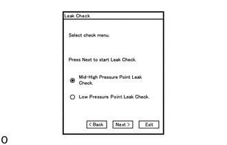
Select Mid-High Pressure Point Leak Check.
Procedure1
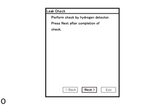
Using SST and a hydrogen gas detector, perform measurements for approximately 10 seconds at the locations where components were removed and installed during the replacement of components.
- SST
- 09401-62020
- NOTICE:
- ·
1.531,1.198 1.156,1.313 1.156,1.313 0.979,1.313 false 1,1.583 1.583,1.583 false 0.438,0.302 0.75,0.458 0.313,0.156 10 false *b 0.469,1.99 0.781,2.146 0.313,0.156 10 false *c 0.677,1.219 0.99,1.375 0.313,0.156 10 false SST 0.813,1.49 1,1.646 0.188,0.156 10 false *d 0.135,0.135 0.448,0.292 0.313,0.156 10 false *a
*a Hydrogen Gas Detector Contact Location and Direction *b Side View *c Cutaway View *d Hydrogen Gas Detector
To perform the measurement, hold the tip of the hydrogen gas detector as shown in the illustration (*c), in contact with a single location from any one of the directions shown.
·Hold the tip in light contact with the location so that the tip does not deform.
- HINT:
- ·
Immediately after the measurement starts, the measured value may be unstable.
·If the measured value is outside of the specification, replace the leaking component with a new one.
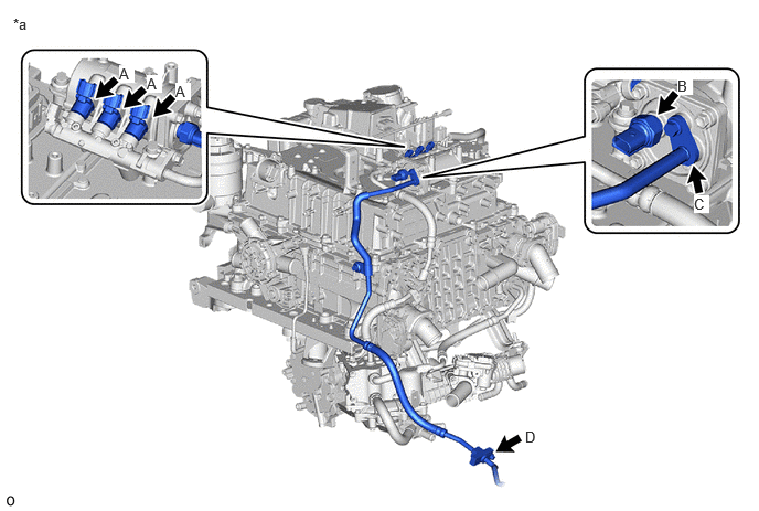
| *a | FC Stack-side Measurement Location | - | - |
| Illustration Item | Measurement Location | Measurement Method | Specified Value |
|---|---|---|---|
| A | Connection between Hydrogen Supply Primary Pipe Sub-assembly x Fuel Injector Assembly | Measure the area near the piping, connecting portion, or sensor connecting portion. | Less than 500 ppm |
| B | Connection between Hydrogen Supply Primary Pressure Sensor x Hydrogen Supply Primary Pipe Sub-assembly | ||
| C | Connection between No. 1 Hydrogen Supply Tube x Hydrogen Supply Primary Pipe Sub-assembly | ||
| D | Connection between No. 1 Hydrogen Supply Tube x No. 2 Hydrogen Supply Tube |
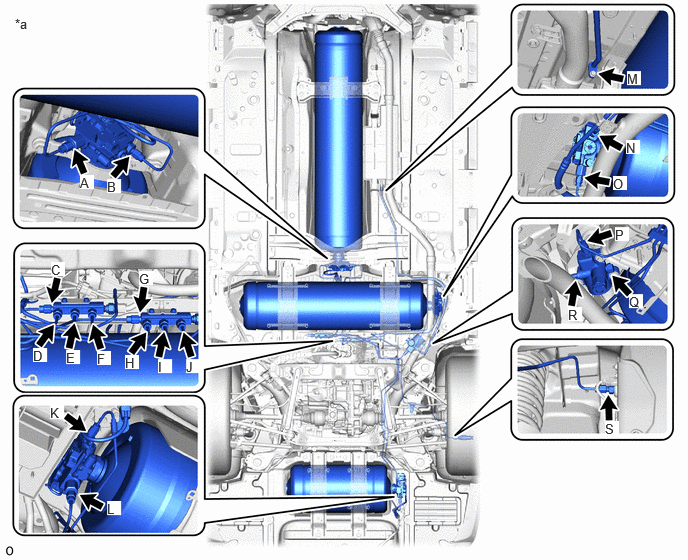
| *a | Hydrogen Tank-side Measurement Location | - | - |
| Illustration Item | Measurement Location | Measurement Method | Specified Value |
|---|---|---|---|
|
*1: If the value is not as specified, replace the O-ring of the medium pressure port. |
|||
| A | Connection between No. 2 Hydrogen Tank Tube and No. 1 Hydrogen Tank Assembly | Measure the area near the piping, connecting portion, or sensor connecting portion. | Less than 500 ppm |
| B | Connection between No. 5 Hydrogen Tank Tube and No. 1 Hydrogen Tank Assembly | ||
| C | Connection between No. 3 Hydrogen Tank Tube and Hydrogen Tank Tube Joint Assembly (for Inlet Side) | ||
| D | Connection between No. 1 Hydrogen Tank Tube and Hydrogen Tank Tube Joint Assembly (for Inlet Side) | ||
| E | Connection between No. 4 Hydrogen Tank Tube and Hydrogen Tank Tube Joint Assembly (for Inlet Side) | ||
| F | Connection between No. 2 Hydrogen Tank Tube and Hydrogen Tank Tube Joint Assembly (for Inlet Side) | ||
| G | Connection between No. 6 Hydrogen Tank Tube and Hydrogen Tank Tube Joint Assembly (for Outlet Side) | ||
| H | Connection between No. 8 Hydrogen Tank Tube and Hydrogen Tank Tube Joint Assembly (for Outlet Side) | ||
| I | Connection between No. 7 Hydrogen Tank Tube and Hydrogen Tank Tube Joint Assembly (for Outlet Side) | ||
| J | Connection between No. 5 Hydrogen Tank Tube and Hydrogen Tank Tube Joint Assembly (for Outlet Side) | ||
| K | Connection between No. 7 Hydrogen Tank Tube and No. 3 Hydrogen Tank Assembly | ||
| L | Connection between No. 4 Hydrogen Tank Tube and No. 3 Hydrogen Tank Assembly | ||
| M | Connection between No. 2 Hydrogen Supply Tube Sub-assembly and No. 3 Hydrogen Supply Tube Sub-assembly | ||
| N | Connection between No. 6 Hydrogen Tank Tube and No. 2 Hydrogen Tank Assembly | ||
| O | Connection between No. 3 Hydrogen Tank Tube and No. 2 Hydrogen Tank Assembly | ||
| P | Connection between No. 8 Hydrogen Tank Tube and Hydrogen Supply Regulator | ||
| Q | Medium Pressure Port of Hydrogen Supply Regulator
*1 |
||
| R | Connection between No. 3 Hydrogen Supply Tube Sub-assembly and Hydrogen Supply Regulator | ||
| S | Connection between No. 1 Hydrogen Tank Tube and Hydrogen Inlet Receptacle | ||
Post-procedure1
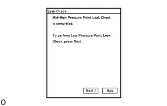
The hydrogen gas leak check is complete.