HEATING / AIR CONDITIONING AIR CONDITIONING SYSTEM Operation not Accepted Even If Air Conditioning Switch is Operated
DESCRIPTION
If the air conditioning system does not operate even when the air conditioning control assembly is operated, the following causes are possible.
| Symptom | Factor |
|---|---|
| Operations are never accepted by the air conditioning control assembly
(With the exception of the switch indicator, everything is turned off) |
·
LIN communication malfunction between air conditioning amplifier assembly and air conditioning control assembly ·
Air conditioning amplifier assembly malfunction (+B or GND circuit) ·
Air conditioning amplifier assembly malfunction ·
Air conditioning control assembly malfunction |
| Operations are never accepted by the cooler control switch assembly (for 3 Zone)
(With the exception of the switch indicator, everything is turned off) |
·
LIN communication malfunction between air conditioning amplifier assembly and cooler control switch assembly ·
Air conditioning amplifier assembly malfunction (+B and GND circuit) ·
Cooler control switch assembly malfunction |
WIRING DIAGRAM
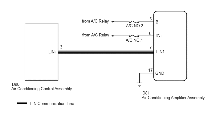
CAUTION / NOTICE / HINT
- NOTICE:
- ·
Inspect the fuses for circuits related to this system before performing the following procedure.
·If DTC B14B3 is output at the same time, troubleshoot for DTC B14B2 first.
PROCEDURE
Check for DTCs.
- Body Electrical > Air Conditioner > Trouble Codes
- 50001 121
- OK:
DTC B14B2 is not output.
- Result:
Proceed to OK NG
OK
NG
Disconnect the D81 air conditioning amplifier assembly connector.
Measure the resistance according to the value(s) in the table below.
- Standard Resistance:
Tester Connection Condition Specified Condition Click Location & Routing(D81)Location & Routingewd_type=routing;type=c;code=D81
Click Connector(D81)Instrument Panel>Instrument Panel Wire>Air Conditioning Amplifier Assemblyewd_type=component;type=c;code=D81;pinno=17
D81-17 (GND) - Body ground Always Below 1 Ω
Measure the voltage according to the value(s) in the table below.
- Standard Voltage:
Tester Connection Switch Condition Specified Condition Click Location & Routing(D81)Location & Routingewd_type=routing;type=c;code=D81
Click Connector(D81)Instrument Panel>Instrument Panel Wire>Air Conditioning Amplifier Assemblyewd_type=component;type=c;code=D81;pinno=5,6
D81-5 (+B1) - Body ground Ignition switch off 11 to 14 V D81-6 (IG+) - Body ground Ignition switch ON 11 to 14 V D81-6 (IG+) - Body ground Ignition switch off Below 1 V
- Result:
Proceed to OK NG
OK
NG