FC CONTROL FC STACK Forced Electrical Charge Discharge Work
PROCEDURE
- Result:
Proceed to NEXT
NEXT
Remove the bolt and disconnect the No. 2 hydrogen supply tube sub-assembly.

To prevent entry of foreign matter, etc., protect the connector of the No. 2 hydrogen supply tube sub-assembly with a plastic bag, etc.
Check that the container valve of the nitrogen cylinder is closed.
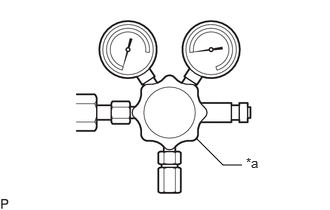
| *a | Regulating Valve |
Check that the regulating valve of the regulator (SST) is closed.
Connect the regulator (SST) to the nitrogen cylinder.
- SST
- 09761-50010 (09761-05010)
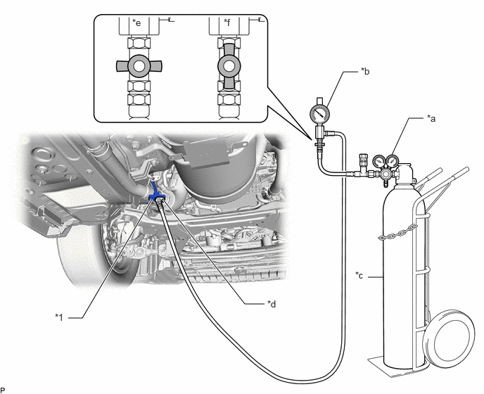
| *1 | No. 1 Hydrogen Supply Tube Sub-assembly | - | - |
| *a | Regulator (SST) | *b | Nitrogen Gas Injector (SST) |
| *c | Nitrogen Cylinder | *d | Tightening Bolt of No. 2 Hydrogen Supply Tube Sub-assembly |
| *e | Close | *f | Open |
Check that the valve of the nitrogen gas injector (SST) is closed.
Connect the nitrogen gas injector (SST) to the regulator (SST).
- SST
- 09406-62010
Connect the nitrogen gas injector (SST) to the No. 1 hydrogen supply tube sub-assembly with the tightening bolt of the No. 2 hydrogen supply tube sub-assembly.
- Torque:
- 10 N*m (102 kgf*cm, 7 ft.*lbf)
Lower the lift.
- Result:
Proceed to NEXT
NEXT
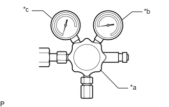
| *a | Regulating Valve |
| *b | Gauge on Right Side of Regulator (SST) |
| *c | Gauge on Left Side of Regulator (SST) |
Open the container valve of the nitrogen cylinder.
- HINT:
-
The pressure of the gauge on the right side of the regulator (SST) increases.
While operating the regulating valve of the regulator (SST), close the container valve of the nitrogen cylinder so that the pressure is 0.9 MPa.
- HINT:
-
Check from the pressure of the gauge on the left side of the regulator (SST).
After 10 minutes have passed, check that the pressure has not decreased.
- HINT:
-
If the pressure has decreased, check the connection of the regulator (SST) and nitrogen gas injector (SST).
Connect the battery charger to the auxiliary battery.
- Result:
Proceed to NEXT
NEXT
Connect the GTS to the DLC3.
Turn the ignition switch to ON.
Turn the GTS on.
Enter the following menus: Powertrain / EV / Utility / FC Stack Electric Charge Release
- Powertrain > EV > Utility
-
Tester Display FC Stack Electric Charge Release - 50005 397 4669
- NOTICE:
- ·
In Utility, do not open or close the container valve of the nitrogen cylinder until instructed on the GTS monitor screen.
·When an abnormal end is displayed on the monitor screen in Utility, stop forced electrical charge discharge immediately.
- HINT:
-
When the instruction for opening the container valve of the nitrogen cylinder is displayed in Utility, operate the regulating valve of the regulator (SST) and adjust the value of the nitrogen gas injector (SST) gauge to 0.9 MPa.
After Utility ends, check again that the container valve of the nitrogen cylinder is closed.
- Result:
Result Proceed to Normal end OK Abnormal end NG
OK
NG
- CAUTION:
-
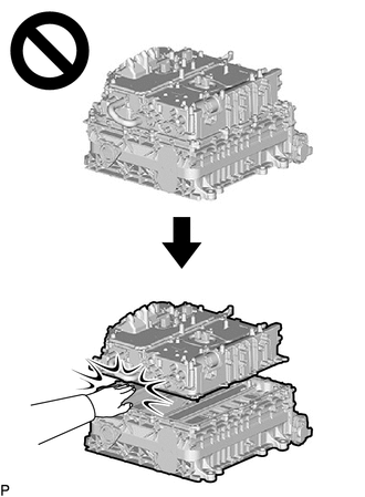
- ·
Since high voltage accumulates within the FC stack assembly with FC converter, never perform the work of separating the FC stack assembly with FC converter into the FC converter assembly and FC stack assembly without first performing electrical charge discharge (electrical charge self-discharge), because doing so is dangerous.
·Removing and installing the FC stack assembly without first discharging the electrical charge may result in an electric shock due to the high voltage circuit.
Close the container valve of the nitrogen cylinder.
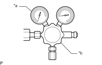
| *a | Gauge on Left Side of Regulator (SST) |
| *b | Regulating Valve |
Close the regulating valve of the regulator (SST).
Close the valve of the nitrogen gas injector (SST).
Gradually loosen the connection of the regulator (SST) and nitrogen gas injector (SST) to remove the nitrogen pressure inside the connected devices.
- HINT:
-
Be sure to perform this work because it removes the nitrogen pressure inside the connected devices.
Remove the nitrogen gas injector (SST) from the regulator (SST).
Gradually open the valve of the nitrogen gas injector (SST) to remove the pressure from the vehicle side.
Remove the tightening bolt of the No. 2 hydrogen supply tube sub-assembly, and then disconnect the nitrogen gas injector (SST) from the No. 1 hydrogen supply tube sub-assembly.
Restart the procedure from "Step 35. Precaution" and perform the procedure up to "Step 164. Perform Electrical Charge Self-discharge (When Forced Electrical Charge Discharge Not Possible)".
- CAUTION:
-
Since the stack voltage cannot be checked while it is installed in the vehicle, never perform the work without first lowering the FC stack assembly with FC converter with front frame assembly from the vehicle.
- HINT:
-
Perform electrical charge self-discharge after lowering the FC stack assembly with FC converter with front frame assembly from the vehicle.
Close the container valve of the nitrogen cylinder.
| *a | Gauge on Left Side of Regulator (SST) |
| *b | Regulating Valve |
Close the regulating valve of the regulator (SST).
Close the valve of the nitrogen gas injector (SST).
Gradually loosen the connection of the regulator (SST) and nitrogen gas injector (SST) to remove the nitrogen pressure inside the connected devices.
- HINT:
-
Be sure to perform this work because it removes the nitrogen pressure inside the connected devices.
Remove the nitrogen gas injector (SST) from the regulator (SST).
Gradually open the valve of the nitrogen gas injector (SST) to remove the pressure from the vehicle side.
Remove the tightening bolt of the No. 2 hydrogen supply tube sub-assembly, and then disconnect the nitrogen gas injector (SST) from the No. 1 hydrogen supply tube sub-assembly.
Protect the openings of the No. 1 hydrogen supply tube sub-assembly with protective tape(non-residue type) to prevent the entry of foreign matter or water.
- Result:
Proceed to NEXT
NEXT
After ending forced electrical charge discharge, restart the procedure from "Step 35. Precaution".
Click hereEngine / Hybrid System>FC CONTROL>FC STACK>REMOVAL