FC CONTROL FC STACK REMOVAL
CAUTION / NOTICE / HINT
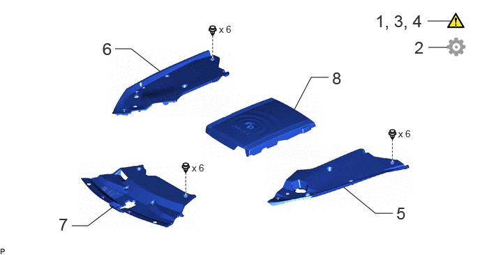
| Procedure | Part Name Code | 
|

|

|
|
|---|---|---|---|---|---|
| 1 | CAUTIONS FOR HIGH VOLTAGE SYSTEM COMPONENTS | - | ( ) |
- | - |
| 2 | CAUTIONS FOR COMPRESSED HYDROGEN GAS | - | - | - | ()
|
| 3 | CAUTIONS FOR COOLANT (TOYOTA GENUINE FC STACK COOLANT (Pre-mixed)) | - | ()
|
- | - |
| 4 | CHECK FOR DTC | - | ()
|
- | - |
| 5 | UPPER RADIATOR SUPPORT SEAL | 53292A | - | - | - |
| 6 | RADIATOR COVER PLATE | 53291B | - | - | - |
| 7 | LOWER RADIATOR AIR DEFLECTOR | 53295 | - | - | - |
| 8 | FC STACK COVER SUB-ASSEMBLY | 1A906 | - | - | - |
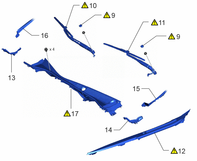
| Procedure | Part Name Code |
|
|
|
|
|---|---|---|---|---|---|
| 9 | FRONT WIPER ARM HEAD CAP | 85292B | ()
|
- | - |
| 10 | FRONT WIPER ARM AND BLADE ASSEMBLY RH | - | ()
|
- | - |
| 11 | FRONT WIPER ARM AND BLADE ASSEMBLY LH | - | ()
|
- | - |
| 12 | FRONT UPPER FENDER PROTECTOR LH | 53826A | ()
|
- | - |
| 13 | COWL TOP VENTILATOR LOUVER PROTECTOR RH | 55782 | - | - | - |
| 14 | COWL TOP VENTILATOR LOUVER PROTECTOR LH | 55783 | - | - | - |
| 15 | LOWER WINDSHIELD MOULDING OUTSIDE LH | 75536D | - | - | - |
| 16 | LOWER WINDSHIELD MOULDING OUTSIDE | 75535A | - | - | - |
| 17 | COWL TOP VENTILATOR LOUVER SUB-ASSEMBLY | 55708 | ()
|
- | - |
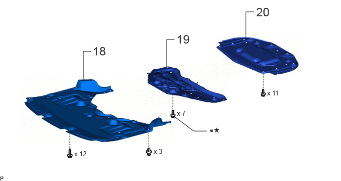
| Procedure | Part Name Code |
|
|
|
|
|---|---|---|---|---|---|
| 18 | FRONT COMPARTMENT UNDER COVER | 51441N | - | - | - |
| 19 | FRONT LOWER SUSPENSION MEMBER PROTECTOR | 51219 | - | - | - |
| 20 | FRONT COMPARTMENT UNDER COVER ASSEMBLY | 51420A | - | - | - |
| ● | Non-reusable part | ★ | Precoated part |
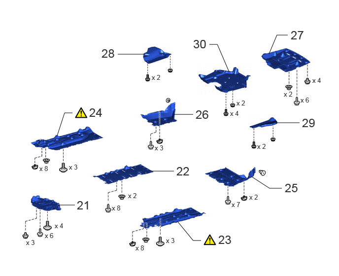
| Procedure | Part Name Code |
|
|
|
|
|---|---|---|---|---|---|
| 21 | REAR NO. 4 FLOOR BOARD SUB-ASSEMBLY | 58404B | - | - | - |
| 22 | REAR NO. 3 FLOOR BOARD SUB-ASSEMBLY | 58403L | - | - | - |
| 23 | REAR NO. 2 FLOOR BOARD SUB-ASSEMBLY | 58402K | ()
|
- | - |
| 24 | REAR NO. 1 FLOOR BOARD SUB-ASSEMBLY | 58401M | ()
|
- | - |
| 25 | REAR FLOOR SIDE MEMBER COVER LH | 57628E | - | - | - |
| 26 | REAR FLOOR SIDE MEMBER COVER RH | 57627G | - | - | - |
| 27 | NO. 1 FLOOR UNDER COVER | 58398F | - | - | - |
| 28 | NO. 1 DIFFERENTIAL SUPPORT PROTECTOR | 52383E | - | - | - |
| 29 | NO. 2 DIFFERENTIAL SUPPORT PROTECTOR | 52384C | - | - | - |
| 30 | REAR SUSPENSION BRACE COVER | 53661B | - | - | - |
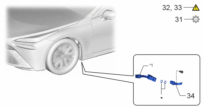
| Procedure | Part Name Code |
|
|
|
|
|---|---|---|---|---|---|
| 31 | PRESSURE RELEASE OPERATION (for Low Pressure and Medium Pressure) | - | - | - | ()
|
| 32 | DETERMINE DISCHARGING METHOD | - | ()
|
- | - |
| 33 | PERFORM FORCED DISCHARGE (WHEN FORCED DISCHARGE POSSIBLE) | - | ()
|
- | - |
| 34 | NO. 2 HYDROGEN SUPPLY TUBE SUB-ASSEMBLY | 77B0E | - | - | - |
| *1 | NO. 1 HYDROGEN SUPPLY TUBE SUB-ASSEMBLY | - | - |
| ● | Non-reusable part | - | - |
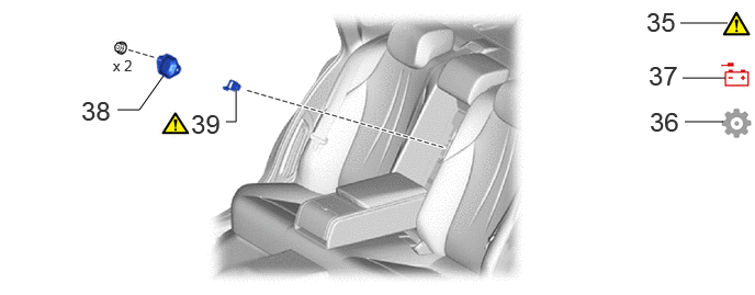
| Procedure | Part Name Code |
|
|
|
|
|---|---|---|---|---|---|
| 35 | PRECAUTION | - | ()
|
- | - |
| 36 | DISABLE BRAKE CONTROL | - | - | - | ()
|
| 37 | DISCONNECT CABLE FROM NEGATIVE AUXILIARY BATTERY TERMINAL | - | - | - | - |
| 38 | NO. 8 EV BATTERY SHIELD PANEL | G92QAA | - | - | - |
| 39 | SERVICE PLUG GRIP | G3834 | ()
|
- | - |
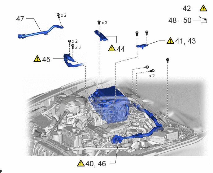
| Procedure | Part Name Code |
|
|
|
|
|---|---|---|---|---|---|
| 40 | DISCONNECT FC CONVERTER POWER OUTLET CABLE (INVERTER WITH CONVERTER ASSEMBLY) | G9200A | ()
|
- | - |
| 41 | REMOVE CONNECTOR COVER ASSEMBLY | - | ()
|
- | - |
| 42 | CHECK TERMINAL VOLTAGE | - | ()
|
- | - |
| 43 | TEMPORARILY INSTALL CONNECTOR COVER ASSEMBLY | - | ()
|
- | - |
| 44 | INVERTER TERMINAL COVER | G9223B | ()
|
- | - |
| 45 | FC AIR COMPRESSOR MOTOR CABLE ASSEMBLY | 17A90 | ()
|
- | - |
| 46 | DISCONNECT FC CONVERTER POWER OUTLET CABLE (INVERTER WITH CONVERTER ASSEMBLY) | G9200A | ()
|
- | - |
| 47 | FENDER APRON BRACE SUB-ASSEMBLY RH | 53705F | - | - | - |
| 48 | DRAIN COOLANT (TOYOTA GENUINE FC STACK COOLANT (Pre-mixed)) | - | - | ()
|
- |
| 49 | DRAIN COOLANT (for Inverter) | - | - | ()
|
- |
| 50 | RECOVER REFRIGERANT FROM REFRIGERATION SYSTEM | - | - | ()
|
- |
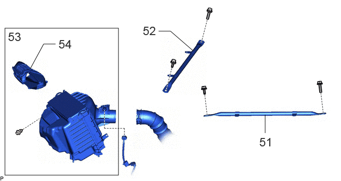
| Procedure | Part Name Code |
|
|
|
|
|---|---|---|---|---|---|
| 51 | RADIATOR SUPPORT TO CROSS MEMBER BRACE SUB-ASSEMBLY LH | 53204E | - | - | - |
| 52 | RADIATOR SUPPORT TO CROSS MEMBER BRACE SUB-ASSEMBLY RH | 53209F | - | - | - |
| 53 | AIR CLEANER WITH ELEMENT ASSEMBLY WITH AIR CLEANER INLET | - | - | - | - |
| 54 | AIR CLEANER INLET | 17751B | - | - | - |
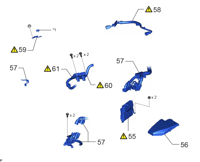
| Procedure | Part Name Code |
|
|
|
|
|---|---|---|---|---|---|
| 55 | FC CONTROL ECU | 898A1 | ()
|
- | - |
| 56 | NO. 2 RELAY BLOCK COVER | 82662B | - | - | - |
| 57 | WIRE HARNESS | - | - | - | - |
| 58 | NO. 1 BATTERY PACK WIRE | 821H3A | ()
|
- | - |
| 59 | NO. 4 FC JUNCTION CABLE BRACKET | G9A84C | ()
|
- | - |
| 60 | FLOOR UNDER WIRE | 821H1 | ()
|
- | - |
| 61 | FC JUNCTION CABLE | G9A2C | ()
|
- | - |
| *1 | BATTERY COVER LOCK STRIKER | - | - |
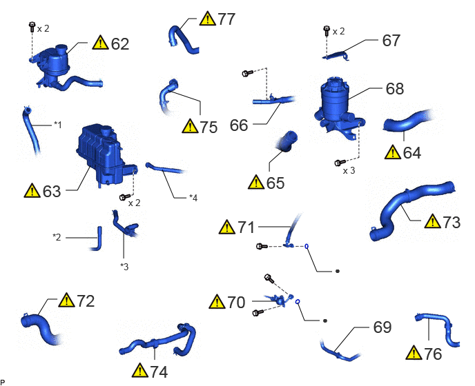
| Procedure | Part Name Code |
|
|
|
|
|---|---|---|---|---|---|
| 62 | EV RESERVE TANK ASSEMBLY | G91H0D | ()
|
- | - |
| 63 | FC RADIATOR RESERVE TANK ASSEMBLY | 16470N | ()
|
- | - |
| 64 | NO. 9 FC RADIATOR HOSE | 16579A | ()
|
- | - |
| 65 | NO. 13 FC RADIATOR HOSE | 1657D | ()
|
- | - |
| 66 | NO. 4 FC INVERTER COOLING PIPE | G91D4 | - | - | - |
| 67 | FC COOLING WATER ION EXCHANGER BRACKET | 16A45 | - | - | - |
| 68 | FC COOLING WATER ION EXCHANGER ASSEMBLY | 16A40 | - | - | - |
| 69 | NO. 15 FC INVERTER COOLING HOSE | G91CF | - | - | - |
| 70 | NO. 1 DISCHARGE HOSE SUB-ASSEMBLY | 88703A | ()
|
- | - |
| 71 | SUCTION HOSE SUB-ASSEMBLY A | 88704A | ()
|
- | - |
| 72 | NO. 1 FC RADIATOR HOSE | 16571G | ()
|
- | - |
| 73 | NO. 7 FC RADIATOR HOSE | 16577D | ()
|
- | - |
| 74 | NO. 13 FC INVERTER COOLING HOSE | G91CD | ()
|
- | - |
| 75 | NO. 1 FC INVERTER COOLING HOSE SUB-ASSEMBLY | G90A1 | ()
|
- | - |
| 76 | WATER HOSE SUB-ASSEMBLY C | 87209C | ()
|
- | - |
| 77 | WATER HOSE SUB-ASSEMBLY E | 87209E | ()
|
- | - |
| *1 | NO. 7 FC INVERTER COOLING HOSE | *2 | RESERVE TANK OUTLET HOSE |
| *3 | RADIATOR TO RESERVE TANK HOSE | *4 | RESERVE TANK INLET HOSE |
| ● | Non-reusable part | - | - |
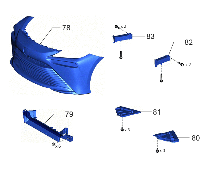
| Procedure | Part Name Code |
|
|
|
|
|---|---|---|---|---|---|
| 78 | FRONT BUMPER COVER | 52119A | - | - | - |
| 79 | NO. 2 FRONT BUMPER REINFORCEMENT SUB-ASSEMBLY | 52029B | - | - | - |
| 80 | RADIATOR SUPPORT EXTENSION LH | 53288B | - | - | - |
| 81 | RADIATOR SUPPORT EXTENSION RH | 53287B | - | - | - |
| 82 | REAR FRAME SIDE RAIL LH | 51116 | - | - | - |
| 83 | REAR FRAME SIDE RAIL RH | 51115 | - | - | - |
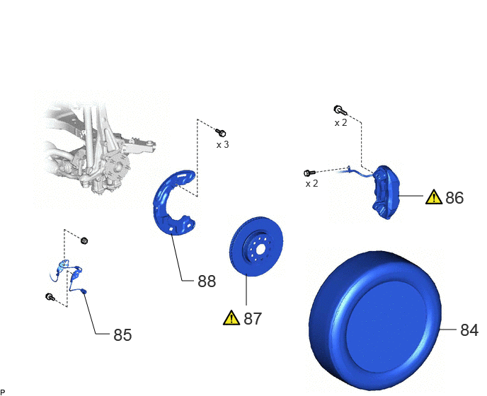
| Procedure | Part Name Code |
|
|
|
|
|---|---|---|---|---|---|
| 84 | FRONT WHEEL LH | - | - | - | - |
| 85 | FRONT SKID CONTROL SENSOR WIRE LH | 89516F | - | - | - |
| 86 | DISC BRAKE CYLINDER ASSEMBLY LH | 47750 | ()
|
- | - |
| 87 | FRONT DISC LH | 43512 | ()
|
- | - |
| 88 | FRONT DISC BRAKE DUST COVER LH | 47782 | - | - | - |
| Procedure | Part Name Code |
|
|
|
|
|---|---|---|---|---|---|
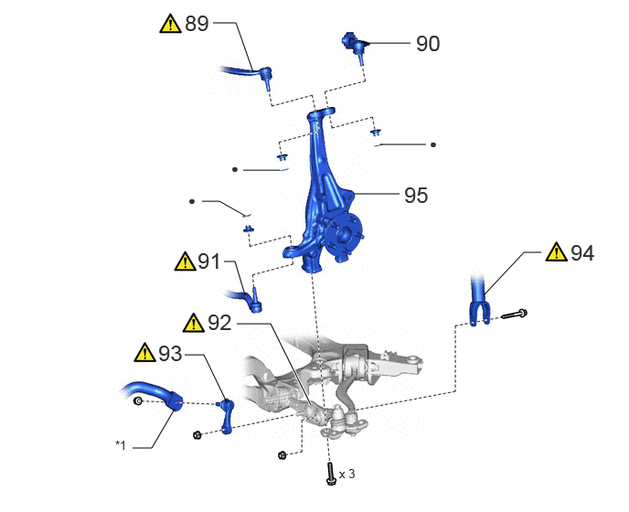
| 89 | FRONT UPPER NO. 1 SUSPENSION ARM ASSEMBLY LH | 48630D | ()
|
- | - |
| 90 | FRONT UPPER NO. 2 SUSPENSION ARM ASSEMBLY LH | 48630E | - | - | - |
| 91 | TIE ROD ASSEMBLY LH | 45470 | ()
|
- | - |
| 92 | FRONT LOWER SUSPENSION ARM ASSEMBLY LH | 48640 | ()
|
- | - |
| 93 | FRONT STABILIZER LINK ASSEMBLY LH | 48810 | ()
|
- | - |
| 94 | FRONT SHOCK ABSORBER ASSEMBLY LH | 48520 | ()
|
- | - |
| 95 | STEERING KNUCKLE LH | 43212 | - | - | - |
| *1 | FRONT STABILIZER BAR | - | - |
| ● | Non-reusable part | - | - |
| Procedure | Part Name Code |
|
|
|
|
|---|---|---|---|---|---|
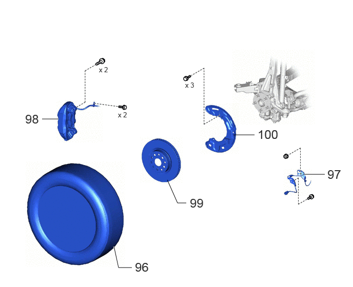
| 96 | FRONT WHEEL RH | - | - | - | - |
| 97 | FRONT SKID CONTROL SENSOR WIRE RH | 89516E | - | - | - |
| 98 | DISC BRAKE CYLINDER ASSEMBLY RH | 47730 | - | - | - |
| 99 | FRONT DISC RH | 43512 | - | - | - |
| 100 | FRONT DISC BRAKE DUST COVER RH | 47781 | - | - | - |
| Procedure | Part Name Code |
|
|
|
|
|---|---|---|---|---|---|
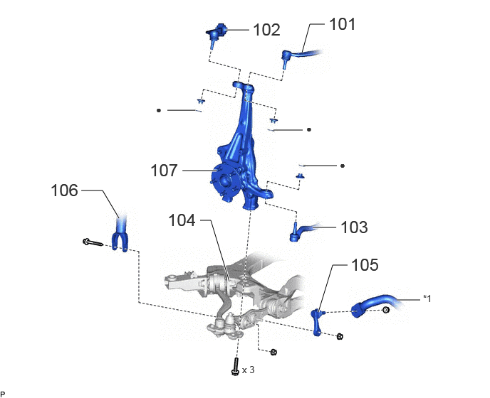
| 101 | FRONT UPPER NO. 1 SUSPENSION ARM ASSEMBLY RH | 48610H | - | - | - |
| 102 | FRONT UPPER NO. 2 SUSPENSION ARM ASSEMBLY RH | 48610J | - | - | - |
| 103 | TIE ROD ASSEMBLY RH | 45460 | - | - | - |
| 104 | FRONT LOWER SUSPENSION ARM ASSEMBLY RH | 48620 | - | - | - |
| 105 | FRONT STABILIZER LINK ASSEMBLY RH | 48820B | - | - | - |
| 106 | FRONT SHOCK ABSORBER ASSEMBLY RH | 48510 | - | - | - |
| 107 | STEERING KNUCKLE RH | 43211 | - | - | - |
| *1 | FRONT STABILIZER BAR | - | - |
| ● | Non-reusable part | - | - |
| Procedure | Part Name Code |
|
|
|
|
|---|---|---|---|---|---|
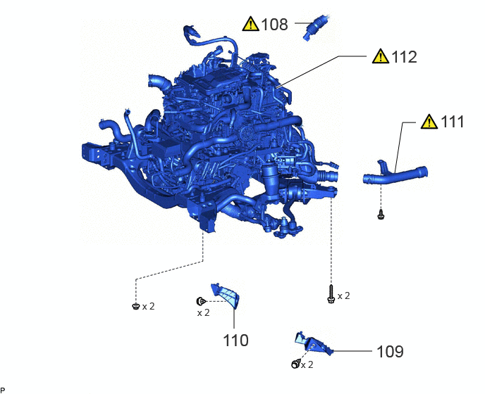
| 108 | NO. 2 STEERING INTERMEDIATE SHAFT ASSEMBLY | 45260 | ()
|
- | - |
| 109 | FRONT COMPARTMENT SIDE COVER LH | 51474C | - | - | - |
| 110 | FRONT COMPARTMENT SIDE COVER RH | 51473D | - | - | - |
| 111 | NO. 1 FC EXHAUST PIPE | 17DB1 | ()
|
- | - |
| 112 | FC CONVERTER WITH FC STACK ASSEMBLY WITH FRONT FRAME ASSEMBLY | - | ()
|
- | - |
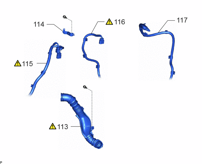
| Procedure | Part Name Code |
|
|
|
|
|---|---|---|---|---|---|
| 113 | AIR CLEANER HOSE ASSEMBLY | 17880D | ()
|
- | - |
| 114 | WIRE HARNESS CLAMP BRACKET | - | - | - | - |
| 115 | FC COOLING WATER PUMP CABLE | 16A18 | ()
|
- | - |
| 116 | HYDROGEN RECIRCULATION PUMP CABLE | - | ()
|
- | - |
| 117 | FC AIR COMPRESSOR MOTOR CABLE ASSEMBLY | 17A90 | - | - | - |
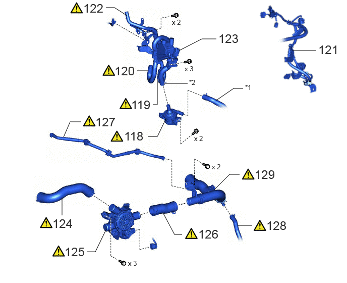
| Procedure | Part Name Code |
|
|
|
|
|---|---|---|---|---|---|
| 118 | WATER PUMP ASSEMBLY WITH MOTOR | G9040D | ()
|
- | - |
| 119 | WATER HOSE | 87209 | ()
|
- | - |
| 120 | HEATER ACCESSORY ASSEMBLY | 87200D | ()
|
- | - |
| 121 | WIRE HARNESS | - | - | - | - |
| 122 | WATER HOSE SUB-ASSEMBLY D | 87209D | ()
|
- | - |
| 123 | HEATER ACCESSORY ASSEMBLY WITH WATER HOSE SUB-ASSEMBLY D | - | - | - | - |
| 124 | NO. 9 FC RADIATOR HOSE | 16579A | ()
|
- | - |
| 125 | FC COOLING WATER TEMPERATURE CONTROL VALVE | 16A31 | ()
|
- | - |
| 126 | NO. 6 FC RADIATOR HOSE | 16576B | ()
|
- | - |
| 127 | RESERVE TANK INLET HOSE | 16565C | ()
|
- | - |
| 128 | NO. 3 FC INTERCOOLER HOSE | 165A3 | ()
|
- | - |
| 129 | NO. 3 FC RADIATOR PIPE AND NO. 4 FC RADIATOR PIPE | - | ()
|
- | - |
| *1 | WATER HOSE | *2 | HEATER ACCESSORY ASSEMBLY |
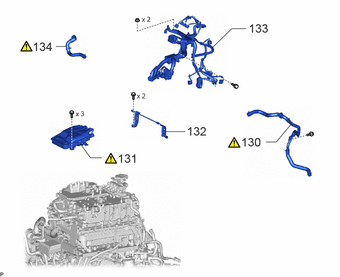
| Procedure | Part Name Code |
|
|
|
|
|---|---|---|---|---|---|
| 130 | WATER HOSE SUB-ASSEMBLY B | 87209B | ()
|
- | - |
| 131 | ELECTRIC HEATER SUB-ASSEMBLY | 87101G | ()
|
- | - |
| 132 | FC STACK COVER BRACKET | 1A911 | - | - | - |
| 133 | WIRE HARNESS | - | - | - | - |
| 134 | NO. 1 FC INVERTER COOLING HOSE SUB-ASSEMBLY | G90A1 | ()
|
- | - |
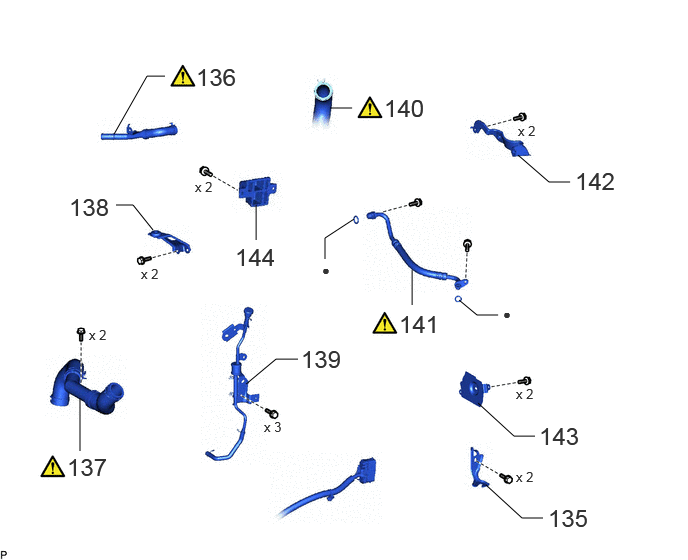
| Procedure | Part Name Code |
|
|
|
|
|---|---|---|---|---|---|
| 135 | NO. 2 HYDROGEN PUMP BRACKET | 23C13 | - | - | - |
| 136 | NO. 5 FC INVERTER COOLING HOSE | G91C5 | ()
|
- | - |
| 137 | NO. 6 FC RADIATOR PIPE | 165H6 | ()
|
- | - |
| 138 | RADIATOR RESERVE TANK BRACKET | 16611C | - | - | - |
| 139 | FC AIR COMPRESSOR BREATHER ASSEMBLY | 17A40A | - | - | - |
| 140 | NO. 3 FC RADIATOR HOSE | 16573D | ()
|
- | - |
| 141 | NO. 3 HYDROGEN TUBE | 23B13 | ()
|
- | - |
| 142 | WATER PUMP BRACKET | 87121W | - | - | - |
| 143 | FC CONVERTER SUPPORT PLATE | G9A76 | - | - | - |
| 144 | FC CONVERTER SPACER | G9A2E | - | - | - |
| ● | Non-reusable part | - | - |
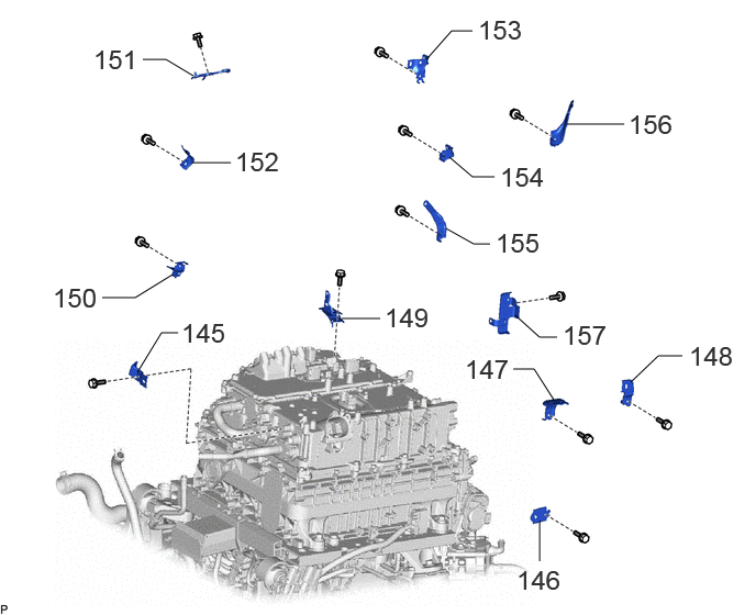
| Procedure | Part Name Code |
|
|
|
|
|---|---|---|---|---|---|
| 145 | NO. 7 RADIATOR HOSE BRACKET | 165F7 | - | - | - |
| 146 | NO. 5 RADIATOR HOSE BRACKET | 165F5 | - | - | - |
| 147 | FC CONVERTER POWER OUTLET BRACKET | G9A25 | - | - | - |
| 148 | NO. 1 HEATER BRACKET | 87452Q | - | - | - |
| 149 | NO. 1 FC COOLING WATER PUMP CABLE BRACKET | 16A1BA | - | - | - |
| 150 | NO. 2 FC COOLING WATER PUMP CABLE BRACKET | 16A1BB | - | - | - |
| 151 | NO. 3 FC JUNCTION CABLE BRACKET | G9A84B | - | - | - |
| 152 | NO. 1 FC JUNCTION CABLE BRACKET | G9A84 | - | - | - |
| 153 | NO. 1 FC WATER AND HYDROGEN PUMP CABLE BRACKET | 16A1AA | - | - | - |
| 154 | NO. 2 FC WATER AND HYDROGEN PUMP CABLE BRACKET | 16A1AB | - | - | - |
| 155 | NO. 3 FC WATER AND HYDROGEN PUMP CABLE BRACKET | 16A1AC | - | - | - |
| 156 | NO. 1 FC AIR COMPRESSOR CABLE BRACKET | 17AA3A | - | - | - |
| 157 | NO. 4 FC AIR COMPRESSOR CABLE BRACKET | 17AA3D | - | - | - |
| Procedure | Part Name Code |
|
|
|
|
|---|---|---|---|---|---|
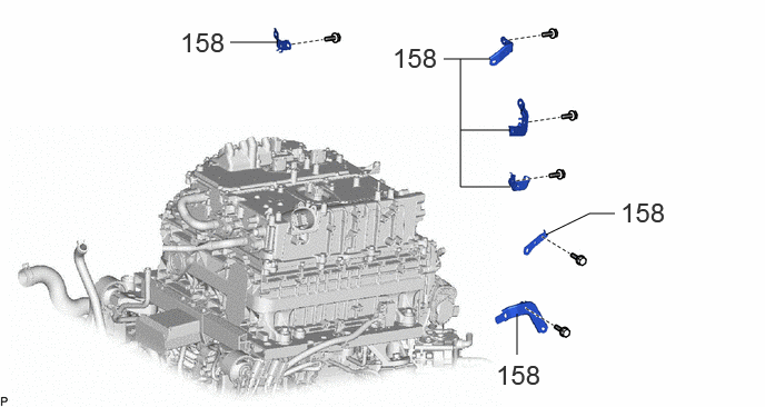
| 158 | WIRE HARNESS CLAMP BRACKET | - | - | - | - |
| Procedure | Part Name Code |
|
|
|
|
|---|---|---|---|---|---|
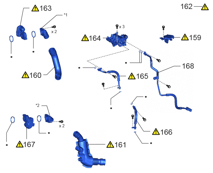
| 159 | HYDROGEN DETECTOR | G4151 | ()
|
- | - |
| 160 | FC STACK AIR INLET HOSE | 17B21 | ()
|
- | - |
| 161 | FC STACK AIR OUTLET HOSE ASSEMBLY | 17D10 | ()
|
- | - |
| 162 | PERFORM ELECTRICAL CHARGE SELF-DISCHARGE (WHEN FORCED ELECTRICAL CHARGE DISCHARGE NOT POSSIBLE) | - | ()
|
- | - |
| 163 | FC AIR PRESSURE REGULATOR ASSEMBLY (AIR SEALING VALVE) | 17C10 | ()
|
- | - |
| 164 | HYDROGEN SUPPLY PRESSURE REGULATOR ASSEMBLY | 23A30 | ()
|
- | - |
| 165 | NO. 1 HYDROGEN TUBE | 23B11 | ()
|
- | - |
| 166 | NO. 2 HYDROGEN TUBE | 23B12 | ()
|
- | - |
| 167 | FC AIR PRESSURE REGULATOR ASSEMBLY (AIR PRESSURE REGULATING VALVE) | 17C10 | ()
|
- | - |
| 168 | NO. 1 HYDROGEN SUPPLY TUBE SUB-ASSEMBLY | 77B0D | - | - | - |
| *1 | FC STACK AIR INLET PIPE ASSEMBLY | *2 | FC STACK AIR OUTLET PIPE ASSEMBLY |
| ● | Non-reusable part | - | - |
| Procedure | Part Name Code |
|
|
|
|
|---|---|---|---|---|---|
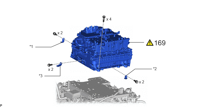
| 169 | FC CONVERTER WITH FC STACK ASSEMBLY | - | ()
|
- | - |
| *1 | FC STACK FRAME SUPPORT BRACKET RH | *2 | FC STACK FRAME SUPPORT BRACKET LH |
| *3 | FRONT FC STACK FRAME SUPPORT BRACKET | - | - |
| Procedure | Part Name Code |
|
|
|
|
|---|---|---|---|---|---|
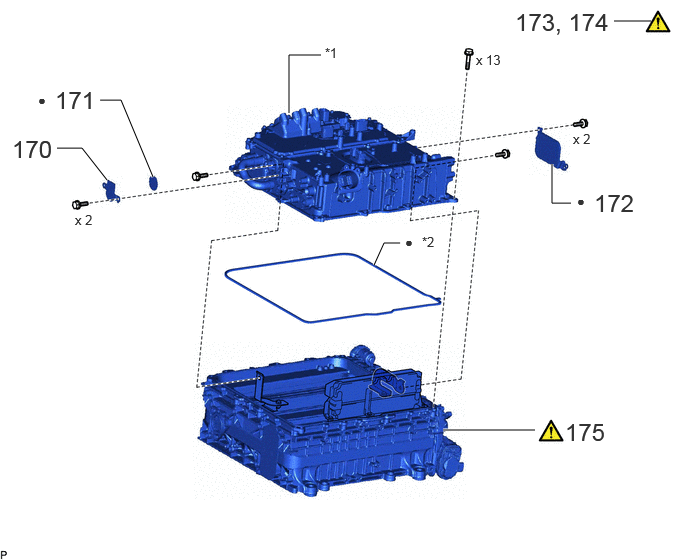
| 170 | FRONT FC CONVERTER SERVICE HOLE COVER | G9A28 | - | - | - |
| 171 | NO. 1 FC STACK CASE PLUG | 1A19A | - | - | - |
| 172 | FC CONVERTER VENT COVER | G9A74 | - | - | - |
| 173 | CLEAN FC CONVERTER WITH FC STACK ASSEMBLY | - | ()
|
- | - |
| 174 | BOLT FALLING PREVENTION WORK (FRONT SIDE (POSITIVE TERMINAL)) | - | ()
|
- | - |
| 175 | FC STACK ASSEMBLY | - | ()
|
- | - |
| *1 | FC CONVERTER ASSEMBLY | *2 | UPPER FC STACK CASE GASKET |
| ● | Non-reusable part | - | - |
CAUTION / NOTICE / HINT
The necessary procedures (adjustment, calibration, initialization, or registration) that must be performed after parts are removed, installed, or replaced during the FC stack assembly removal/installation are shown below.
| Replaced Part or Performed Procedure | Necessary Procedures | Effect/Inoperative Function When Necessary Procedures are not Performed | Link |
|---|---|---|---|
|
*: The vehicle height changes because of suspension or tire replacement. |
|||
| Disconnect cable from negative auxiliary battery terminal | Memorize steering angle neutral point | Parking assist monitor system | ()
|
| Panoramic view monitor system | ()
|
||
| Wheel alignment adjustment | Perform "Calibration" | Electronically controlled brake system malfunctions | ()
|
| Front bumper assembly (Including removal and installation) | ·
Measurement of ultrasonic sensor detection angle ·
Ultrasonic sensor detection angle registration |
·
TOYOTA Parking assist- sensor system ·
Parking support brake system ·
Advanced park |
w/ Advanced Park:
( )
w/o Advanced Park: ( )
|
| Front television camera view adjustment | Panoramic view monitor system | ()
|
|
| Suspension, tires, etc.* | ·
Measurement of ultrasonic sensor detection angle ·
Ultrasonic sensor detection angle registration |
·
Parking support brake system ·
Advanced park |
w/ Advanced Park:
( )
w/o Advanced Park: ( )
|
| Rear television camera assembly optical axis (Back camera position setting) | Parking assist monitor system | ()
|
|
·
Parking assist ECU initialization ·
Adjust steering angle ·
Rear television camera view adjustment (for Rear camera detection system) |
Panoramic view monitor system | ()
|
|
| Perform headlight ECU sub-assembly LH initialization | Automatic headlight beam level control system | ()
|
|
- HINT:
-
When the cable is disconnected/reconnected to the auxiliary battery terminal, systems temporarily stop operating. However, each system has a function that completes learning the first time the system is used.
- ·
Learning completes when vehicle is driven
Effect/Inoperative Function When Necessary Procedures are not Performed Necessary Procedures Link Lane tracing assist system Drive the vehicle straight ahead at 35 km/h (22 mph) or more for 5 seconds or more. ( )
Pre-collision system Adaptive high beam system
·Learning completes when vehicle is operated normally
Effect/Inoperative Function When Necessary Procedures are not Performed Necessary Procedures Link Air conditioning system After the ignition switch is turned to ON, the servo motor and expansion valve standard position is recognized. -
·The procedure listed below is for the LH side.
·Use the same procedure for the RH and LH sides.
- NOTICE:
- ·
Immediately after installing the brake pads, the braking performance may be reduced. Always perform a road test in a safe place while paying attention to the surroundings.
·After replacing the front disc brake pads, the brake pedal may feel soft due to clearance between the front disc brake pads and front disc. Depress the brake pedal several times until the brake pedal feels firm.
·After replacing the front disc brake pads, always perform a road test to check the braking performance and check for vibrations.
·When removing or installing the front disc brake cylinder assembly, pushing back the disc brake piston may cause a large clearance between the brake pads and brake disc. When the brake pedal is depressed with a large clearance between the brake pads and the brake disc, DTC C13DB00, C13DC00, C13DD00, C13DE00, C140000 and/or C140A00 related to abnormal brake fluid pressure may be stored. Make sure to clear any DTCs after performing this procedure.
·While the auxiliary battery is connected, even if the ignition switch is off, the brake control system activates when the brake pedal is depressed or any door courtesy switch turns on. Therefore, when servicing the brake system components, do not operate the brake pedal or open/close the doors while the auxiliary battery is connected.
- CAUTION:
- ·
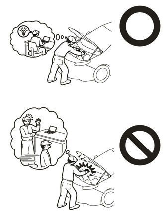
This vehicle contains high voltage circuits standardized with orange colored wiring and connectors, so follow the instructions in this manual to perform the procedures correctly.
Click hereEngine / Hybrid System>HYBRID / BATTERY CONTROL>HYBRID CONTROL SYSTEM>PRECAUTION
·If the correct procedures are not followed according to the instructions in this manual, there is a danger of electric shock from the high voltage circuits.
·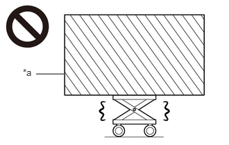 0.542,1.115 0.958,1.115 false 0.344,1.01 0.656,1.208 0.313,0.198 10 false *a
*a Heavy object exceeding the capacity of the engine lifter
Because the weight of the FC stack with FC converter assembly is extremely heavy, make sure to follow the work procedures described in the repair manual.
·If work is not performed according to the procedures described in the repair manual, there is a danger that the engine lifter could drop and components could fall down.
·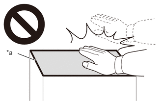 0.375,1.135 0.75,1.281 true 0.135,1.031 0.448,1.229 0.313,0.198 10 false *a
*a High temperature areas
Do not touch the FC stack assembly or its surroundings when they are hot.
·Touching the FC stack assembly or its surroundings when they are hot could result in burns.
·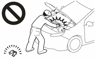
Be sure to wear insulating gloves when working on high voltage wiring or components.
·If work is performed without wearing insulating gloves, there is a danger of electric shock.
·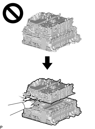
Since high voltage accumulates within the FC stack assembly with FC converter, never perform the work of separating the FC stack assembly with FC converter into the FC converter assembly and FC stack assembly without first performing electrical charge discharge (forced electrical charge discharge or electrical charge self-discharge), because doing so is dangerous.
Click hereEngine / Hybrid System>FC CONTROL>FC STACK>REMOVAL
·Removing and installing the FC stack assembly without first discharging the electrical charge may result in an electric shock due to the high voltage circuit.
PROCEDURE

 1. CAUTIONS FOR HIGH VOLTAGE SYSTEM COMPONENTS
- NOTICE:
- ·
Do not allow foreign matter to enter the opening of the connector.
·Do not touch the connector terminals.
·Do not turn the power switch on (READY) before filling the coolant (for inverter).
·When turning power switch on (IG), do not also turn the power switch on (READY).
·Do not attempt to repair the connector terminal or the threads of the aluminum case.
·Be careful not to drop parts, damage parts with tools, or allow interference or impacts with surrounding components.
·Do not apply excessive force to the wire harnesses.
·Do not apply oil or grease to the bolts.
2. CAUTIONS FOR COMPRESSED HYDROGEN GAS
3. CAUTIONS FOR COOLANT (TOYOTA GENUINE FC STACK COOLANT (Pre-mixed))
4.CHECK FOR DTC
|
|
Click here()
|
53292A
5.REMOVE UPPER RADIATOR SUPPORT SEAL

53291B
6.REMOVE RADIATOR COVER PLATE

53295
7.REMOVE LOWER RADIATOR AIR DEFLECTOR

1A906
8.REMOVE FC STACK COVER SUB-ASSEMBLY
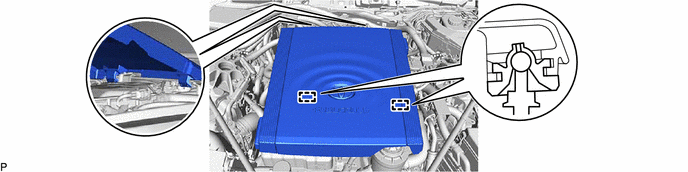
85292B
9.REMOVE FRONT WIPER ARM HEAD CAP
|
|
Click here()
|
10.REMOVE FRONT WIPER ARM AND BLADE ASSEMBLY RH
|
|
()
|
11.REMOVE FRONT WIPER ARM AND BLADE ASSEMBLY LH
|
|
Click here()
|
53826A
12.REMOVE FRONT UPPER FENDER PROTECTOR LH
|
|
Click here()
|
55782
13.REMOVE COWL TOP VENTILATOR LOUVER PROTECTOR RH
55783
14.REMOVE COWL TOP VENTILATOR LOUVER PROTECTOR LH
75536D
15.REMOVE LOWER WINDSHIELD MOULDING OUTSIDE LH
75535A
16.REMOVE LOWER WINDSHIELD MOULDING OUTSIDE
55708
17.REMOVE COWL TOP VENTILATOR LOUVER SUB-ASSEMBLY
|
|
Click here()
|
51441N
18.REMOVE FRONT COMPARTMENT UNDER COVER

51219
19.REMOVE FRONT LOWER SUSPENSION MEMBER PROTECTOR

51420A
20.REMOVE FRONT COMPARTMENT UNDER COVER ASSEMBLY

58404B
21.REMOVE REAR NO. 4 FLOOR BOARD SUB-ASSEMBLY
58403L
22.REMOVE REAR NO. 3 FLOOR BOARD SUB-ASSEMBLY
58402K
23.REMOVE REAR NO. 2 FLOOR BOARD SUB-ASSEMBLY
|
|
Click here()
|
58401M
24.REMOVE REAR NO. 1 FLOOR BOARD SUB-ASSEMBLY
|
|
Click here()
|
57628E
25.REMOVE REAR FLOOR SIDE MEMBER COVER LH
57627G
26.REMOVE REAR FLOOR SIDE MEMBER COVER RH
58398F
27.REMOVE NO. 1 FLOOR UNDER COVER
52383E
28.REMOVE NO. 1 DIFFERENTIAL SUPPORT PROTECTOR
52384C
29.REMOVE NO. 2 DIFFERENTIAL SUPPORT PROTECTOR
53661B
30.REMOVE REAR SUSPENSION BRACE COVER
31. PRESSURE RELEASE OPERATION (for Low Pressure and Medium Pressure)
32. DETERMINE DISCHARGING METHOD
|
|
|
Presence of vehicle external damage (accident)
Check the FC stack assembly and area near the FC stack assembly for any damage that requires body repair or replacement.
Check the FC stack assembly and area near the FC stack assembly for external damage.
Click hereEngine / Hybrid System>FC CONTROL>FC STACK>ON-VEHICLE INSPECTION
- Result:
Result Proceed to NG Perform electrical charge self-discharge. (Perform after lowering the FC stack assembly with FC converter with front frame assembly from the vehicle. Perform the procedure up to "Perform Electrical Charge Self-discharge (When Forced Electrical Charge Discharge Not Possible)".) OK Go to Check No. 1 Hydrogen Supply Tube Sub-assembly and No. 2 Hydrogen Supply Tube Sub-assembly Pipes
Check No. 1 hydrogen supply tube sub-assembly and No. 2 hydrogen supply tube sub-assembly pipes
Check that the required pipes are not cracked, bent or damaged.
- Result:
Result Proceed to NG Perform electrical charge self-discharge. (Perform after lowering the FC stack assembly with FC converter with front frame assembly from the vehicle. Perform the procedure up to "Perform Electrical Charge Self-discharge (When Forced Electrical Charge Discharge Not Possible)".) OK Go to Check HV/EV battery SOC
Check HV/EV battery SOC
Connect the GTS to the DLC3.
Turn the ignition switch to ON.
Enter the following menus: Powertrain / EV / Data List / HV/EV battery SOC.
Check the HV/EV battery SOC.
- Standard Percentage:
30 % or higher
- Result:
Result Proceed to NG Perform electrical charge self-discharge. (Perform after lowering the FC stack assembly with FC converter with front frame assembly from the vehicle. Perform the procedure up to "Perform Electrical Charge Self-discharge (When Forced Electrical Charge Discharge Not Possible)".) OK Go to Perform Forced Electrical Charge Discharge
Click here()
33. PERFORM FORCED DISCHARGE (WHEN FORCED DISCHARGE POSSIBLE)
|
|
|
Go to Perform Forced Electrical Charge Discharge
Click hereEngine / Hybrid System>FC CONTROL>FC STACK>Forced Electrical Charge Discharge Work
77B0E
34.DISCONNECT NO. 2 HYDROGEN SUPPLY TUBE SUB-ASSEMBLY
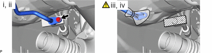
Remove the bolt and No. 2 hydrogen supply tube sub-assembly.
Remove the 2 O-rings from the No. 2 hydrogen supply tube sub-assembly.
Cover the connection of the No. 2 hydrogen supply tube sub-assembly with plastic bags to prevent the foreign matter.
Protect the openings of the No. 1 hydrogen supply tube sub-assembly with protective tape (non-residue type) to prevent the entry of foreign matter or water.
35. PRECAUTION
|
|
|
36.DISABLE BRAKE CONTROL
37.DISCONNECT CABLE FROM NEGATIVE AUXILIARY BATTERY TERMINAL
G92QAA
38.REMOVE NO. 8 EV BATTERY SHIELD PANEL
|
|
Click here()
|
G3834
39.REMOVE SERVICE PLUG GRIP
|
|
Click here()
|
G9200A
40.DISCONNECT FC CONVERTER POWER OUTLET CABLE (INVERTER WITH CONVERTER ASSEMBLY)
|
|
Click here()
|
41.REMOVE CONNECTOR COVER ASSEMBLY
|
|
Click here()
|
42.CHECK TERMINAL VOLTAGE
|
|
Click here()
|
43.TEMPORARILY INSTALL CONNECTOR COVER ASSEMBLY
|
|
Click here()
|
G9223
44.REMOVE INVERTER TERMINAL COVER
|
|
Click here()
|
17A90
45.DISCONNECT FC AIR COMPRESSOR MOTOR CABLE ASSEMBLY
|
|
Click here()
|
G9200A
46.DISCONNECT FC CONVERTER POWER OUTLET CABLE (INVERTER WITH CONVERTER ASSEMBLY)
|
|
Click here()
|
53705F
47.REMOVE FENDER APRON BRACE SUB-ASSEMBLY RH
48.DRAIN COOLANT (TOYOTA GENUINE FC STACK COOLANT (Pre-mixed))
49.DRAIN COOLANT (for Inverter)
50.RECOVER REFRIGERANT FROM REFRIGERATION SYSTEM
for HFC-134a(R134a):
Click hereVehicle Interior>HEATING / AIR CONDITIONING>REFRIGERANT (for HFC-134a(R134a))>REPLACEMENT
for HFO-1234yf(R1234yf):
Click hereVehicle Interior>HEATING / AIR CONDITIONING>REFRIGERANT (for HFO-1234yf(R1234yf))>REPLACEMENT
53204E
51.REMOVE RADIATOR SUPPORT TO CROSS MEMBER BRACE SUB-ASSEMBLY LH

53209F
52.REMOVE RADIATOR SUPPORT TO CROSS MEMBER BRACE SUB-ASSEMBLY RH

53.REMOVE AIR CLEANER WITH ELEMENT ASSEMBLY WITH AIR CLEANER INLET
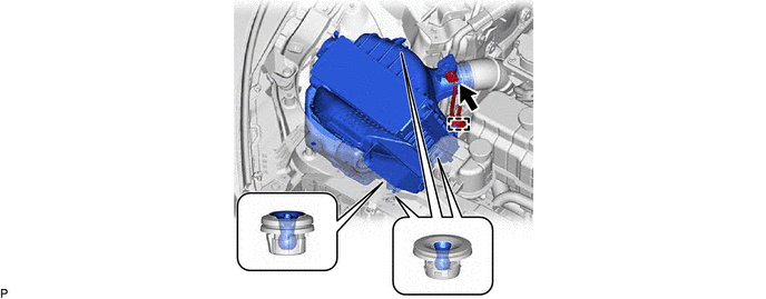
17751B
54.REMOVE AIR CLEANER INLET

898A1
55.REMOVE FC CONTROL ECU
|
|
Click here()
|
82662B
56.REMOVE NO. 2 RELAY BLOCK COVER

57.REMOVE WIRE HARNESS
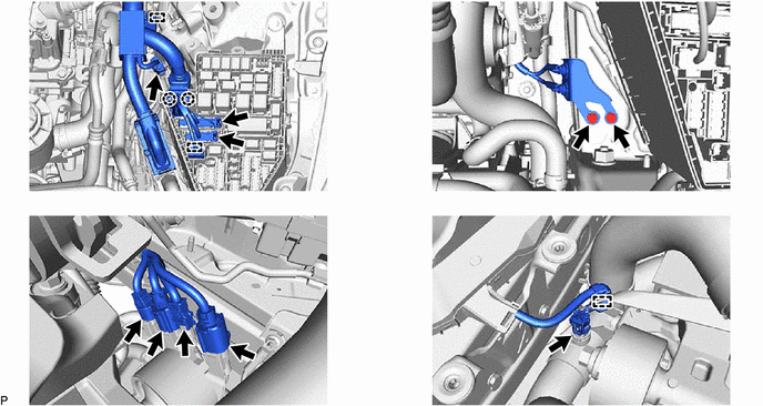
821H3A
58.REMOVE NO. 1 BATTERY PACK WIRE
|
|
Click here()
|
G9A84C
59.REMOVE NO. 4 FC JUNCTION CABLE BRACKET
|
|
Click here()
|
821H1
60.DISCONNECT FLOOR UNDER WIRE
|
|
Click here()
|
G9A2C
61.DISCONNECT FC JUNCTION CABLE
|
|
|
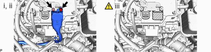
Detach the clamp.
Remove the 2 bolts and disconnect the FC junction cable from the FC converter assembly.
Protect the openings of the FC converter assembly with protective tape (non-residue type) to prevent the entry of foreign matter or water.
G91H0D
62.REMOVE EV RESERVE TANK ASSEMBLY
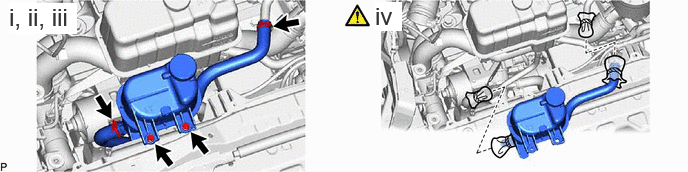
Slide the clip, disconnect the No. 6 FC inverter cooling hose from the No. 4 FC inverter cooling pipe.
Slide the clip, disconnect the No. 7 FC inverter cooling hose from the EV reserve tank assembly.
Remove the 2 bolts and EV reserve tank assembly.
Cover the connection of the EV reserve tank assembly, No. 6 FC inverter cooling hose, No. 7 FC inverter cooling hose and No. 4 FC inverter cooling pipe with plastic bags to prevent the foreign matter.
16470N
63.REMOVE FC RADIATOR RESERVE TANK ASSEMBLY
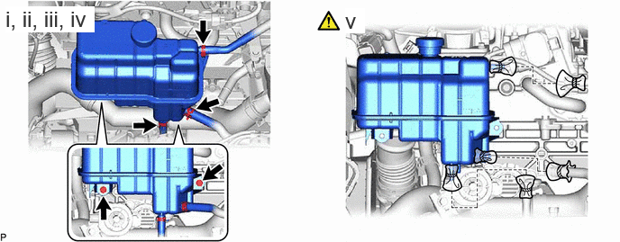
Slide the clip, disconnect the reserve tank inlet hose.
Slide the clip, disconnect the radiator to reserve tank hose.
Slide the clip, disconnect the reserve tank outlet hose.
Remove the 2 bolts and FC radiator reserve tank assembly.
Cover the connection of the FC radiator reserve tank assembly, reserve tank inlet hose, radiator to reserve tank hose and reserve tank outlet hose with plastic bags to prevent the foreign matter.
16579A
64.DISCONNECT NO. 9 FC RADIATOR HOSE
|
|
Click here()
|
1657D
65.DISCONNECT NO. 13 FC RADIATOR HOSE
|
|
Click here()
|
G91D4
66.DISCONNECT NO. 4 FC INVERTER COOLING PIPE
16A45
67.REMOVE FC COOLING WATER ION EXCHANGER BRACKET
16A40
68.REMOVE FC COOLING WATER ION EXCHANGER ASSEMBLY
G91CF
69.DISCONNECT NO. 15 FC INVERTER COOLING HOSE
88703A
70.DISCONNECT NO. 1 DISCHARGE HOSE SUB-ASSEMBLY
|
|
Click here()
|
88704A
71.DISCONNECT SUCTION HOSE SUB-ASSEMBLY A
|
|
Click here()
|
16571G
72.DISCONNECT NO. 1 FC RADIATOR HOSE
|
|
Click here()
|
16577D
73.REMOVE NO. 7 FC RADIATOR HOSE
|
|
Click here()
|
G91CD
74.DISCONNECT NO. 13 FC INVERTER COOLING HOSE
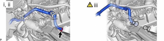
Detach the 2 clamps.
Slide the clip, disconnect the No. 13 FC inverter cooling hose.
Cover the connection of the No. 13 FC inverter cooling hose and FC air compressor with motor assembly with plastic bags to prevent the foreign matter.
G90A1
75.DISCONNECT NO. 1 FC INVERTER COOLING HOSE SUB-ASSEMBLY
|
|
Click here()
|
87209C
76.DISCONNECT WATER HOSE SUB-ASSEMBLY C
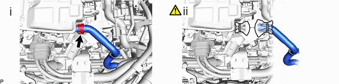
Slide the clip, disconnect the water hose sub-assembly C.
Cover the connection of the water hose sub-assembly C and electric heater sub-assembly with plastic bags to prevent the foreign matter.
87209E
77.DISCONNECT WATER HOSE SUB-ASSEMBLY E
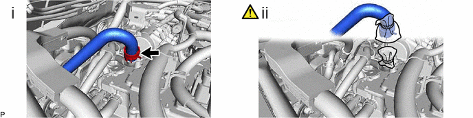
Slide the clip, disconnect the water hose sub-assembly E.
Cover the connection of the water hose sub-assembly E and water hose sub-assembly D with plastic bags to prevent the foreign matter.
52119A
78.REMOVE FRONT BUMPER COVER
52029B
79.REMOVE NO. 2 FRONT BUMPER REINFORCEMENT SUB-ASSEMBLY

53288B
80.REMOVE RADIATOR SUPPORT EXTENSION LH
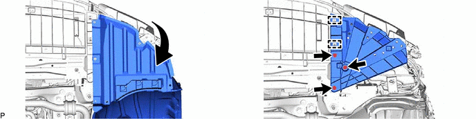
53287B
81.REMOVE RADIATOR SUPPORT EXTENSION RH
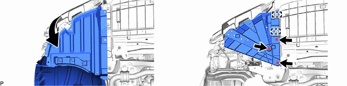
51116
82.REMOVE REAR FRAME SIDE RAIL LH

51115
83.REMOVE REAR FRAME SIDE RAIL RH

84.REMOVE FRONT WHEEL LH
89516F
85.DISCONNECT FRONT SKID CONTROL SENSOR WIRE LH
47750
86.DISCONNECT DISC BRAKE CYLINDER ASSEMBLY LH
|
|
Click here()
|
43512
87.REMOVE FRONT DISC LH
|
|
Click here()
|
47782
88.REMOVE FRONT DISC BRAKE DUST COVER LH
48630D
89.DISCONNECT FRONT UPPER NO. 1 SUSPENSION ARM ASSEMBLY LH
|
|
Click here()
|
48630E
90.DISCONNECT FRONT UPPER NO. 2 SUSPENSION ARM ASSEMBLY LH
Use the same procedure described for the front upper No. 1 suspension arm assembly LH.
45470
91.DISCONNECT TIE ROD ASSEMBLY LH
|
|
Click here()
|
48640
92.LOOSEN FRONT LOWER SUSPENSION ARM ASSEMBLY LH
|
|
Click here()
|
48810
93.REMOVE FRONT STABILIZER LINK ASSEMBLY LH
|
|
Click here()
|
48520
94.DISCONNECT FRONT SHOCK ABSORBER ASSEMBLY LH
|
|
Click here()
|
43212
95.REMOVE STEERING KNUCKLE LH
96.REMOVE FRONT WHEEL RH
89516E
97.DISCONNECT FRONT SKID CONTROL SENSOR WIRE RH
Perform the same procedure as for the LH side.
47730
98.DISCONNECT DISC BRAKE CYLINDER ASSEMBLY RH
Perform the same procedure as for the LH side.
43512
99.REMOVE FRONT DISC RH
Perform the same procedure as for the LH side.
47781
100.REMOVE FRONT DISC BRAKE DUST COVER RH
Perform the same procedure as for the LH side.
48610H
101.DISCONNECT FRONT UPPER NO. 1 SUSPENSION ARM ASSEMBLY RH
Perform the same procedure as for the LH side.
48610J
102.DISCONNECT FRONT UPPER NO. 2 SUSPENSION ARM ASSEMBLY RH
Perform the same procedure as for the LH side.
45460
103.DISCONNECT TIE ROD ASSEMBLY RH
Perform the same procedure as for the LH side.
48620
104.LOOSEN FRONT LOWER SUSPENSION ARM ASSEMBLY RH
Perform the same procedure as for the LH side.
48820B
105.REMOVE FRONT STABILIZER LINK ASSEMBLY RH
Perform the same procedure as for the LH side.
48510
106.DISCONNECT FRONT SHOCK ABSORBER ASSEMBLY RH
Perform the same procedure as for the LH side.
43211
107.REMOVE STEERING KNUCKLE RH
Perform the same procedure as for the LH side.
45260
108.DISCONNECT NO. 2 STEERING INTERMEDIATE SHAFT ASSEMBLY
|
|
Click here()
|
51474C
109.REMOVE FRONT COMPARTMENT SIDE COVER LH
51473D
110.REMOVE FRONT COMPARTMENT SIDE COVER RH
Perform the same procedure as for the LH side.
17DB1
111.REMOVE NO. 1 FC EXHAUST PIPE
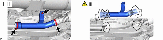
Loosen the 2 hose clamps.
Remove the bolt and No. 1 FC exhaust pipe.
Cover the connection of the No. 1 FC exhaust pipe and FC stack air outlet hose with plastic bags to prevent the foreign matter.
112.REMOVE FC CONVERTER WITH FC STACK ASSEMBLY WITH FRONT FRAME ASSEMBLY
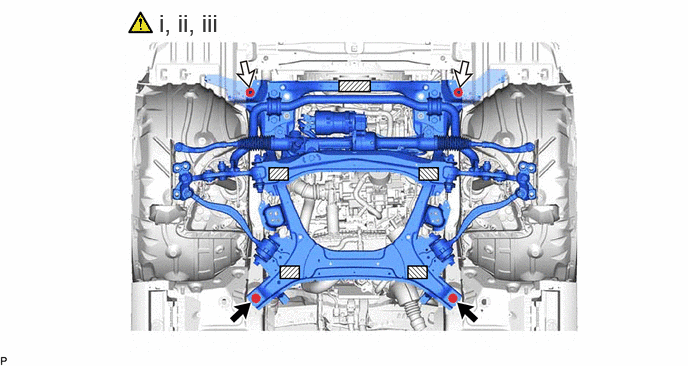

|
Bolt | 
|
Nut |

|
Attachments | - | - |
Set the FC converter with FC stack assembly with front frame assembly on an engine lifter.
- CAUTION:
-
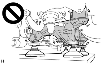
- ·
The FC converter with FC stack assembly with front frame assembly is a heavy component. Make sure that it is supported securely.
·If it is not supported securely, it could fall and result in a serious accident.
- NOTICE:
-
Place wooden blocks or plate lift attachments so that the FC converter with FC stack assembly with front frame assembly is level.
Remove the 2 bolts and 2 nuts.
Operate the engine lifter, then slowly remove the FC converter with FC stack assembly with front frame assembly from the vehicle.
- NOTICE:
- ·
Perform this procedure with several people supporting the FC converter with FC stack assembly with front frame assembly so that it does not tilt or fall.
·Remove while paying attention to the wire harnesses and steering shaft.
17880D
113.REMOVE AIR CLEANER HOSE ASSEMBLY
|
|
Click here()
|
114.REMOVE WIRE HARNESS CLAMP BRACKET

16A18
115.DISCONNECT FC COOLING WATER PUMP CABLE
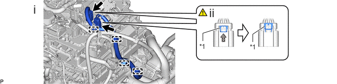
| *1 | Green-colored Lock | - | - |
Detach the 4 clamps.
As shown in the illustration, pull out the green lock of the connector and disconnect the 2 connectors.
116.DISCONNECT HYDROGEN RECIRCULATION PUMP CABLE
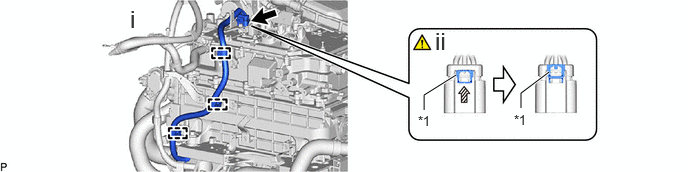
| *1 | Green-colored Lock | - | - |
Detach the 3 clamps.
As shown in the illustration, pull out the green lock of the connector and disconnect the connector.
17A90
117.DISCONNECT FC AIR COMPRESSOR MOTOR CABLE ASSEMBLY

G9040D
118.REMOVE WATER PUMP ASSEMBLY WITH MOTOR
|
|
Click here()
|
119.DISCONNECT WATER HOSE
|
|
Click here()
|
87200D
120.DISCONNECT HEATER ACCESSORY ASSEMBLY
|
|
Click here()
|
121.DISCONNECT WIRE HARNESS
87209D
122.DISCONNECT WATER HOSE SUB-ASSEMBLY D
|
|
Click here()
|
123.REMOVE HEATER ACCESSORY ASSEMBLY WITH WATER HOSE SUB-ASSEMBLY D
16579A
124.REMOVE NO. 9 FC RADIATOR HOSE
|
|
Click here()
|
16A31
125.REMOVE FC COOLING WATER TEMPERATURE CONTROL VALVE
|
|
Click here()
|
16576B
126.REMOVE NO. 6 FC RADIATOR HOSE
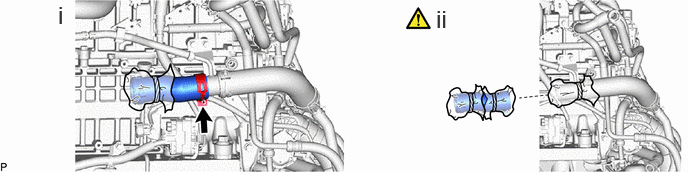
Slide the clip, remove the No. 6 FC radiator hose.
Cover the connection of the No. 6 FC radiator hose and No. 4 FC radiator pipe with plastic bags to prevent the foreign matter.
16565C
127.REMOVE RESERVE TANK INLET HOSE
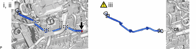
Detach the 3 clamps.
Slide the clip, remove the reserve tank inlet hose.
Cover the connection of the reserve tank inlet hose and No. 4 FC radiator pipe with plastic bags to prevent the foreign matter.
165A3
128.DISCONNECT NO. 3 FC INTERCOOLER HOSE
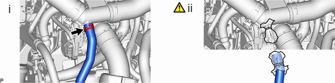
Slide the clip, remove the No. 3 FC intercooler hose.
Cover the connection of the No. 3 FC intercooler hose and No. 3 FC radiator pipe with plastic bags to prevent the foreign matter.
129.REMOVE NO. 3 FC RADIATOR PIPE AND NO. 4 FC RADIATOR PIPE
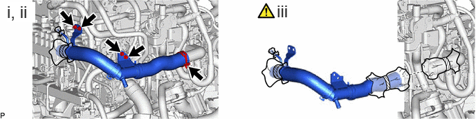
Slide the clip, disconnect the No. 4 FC radiator hose.
Remove the 4 bolts, No. 3 FC radiator pipe and No. 4 FC radiator pipe.
Cover the connection of the No. 4 FC radiator hose and FC stack water outlet with plastic bags to prevent the foreign matter.
87209B
130.REMOVE WATER HOSE SUB-ASSEMBLY B
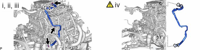
Detach the clamp.
Slide the 2 clips, disconnect the water hose sub-assembly B.
Remove the bolt and water hose sub-assembly B.
Cover the connection of the water hose sub-assembly B, hydrogen recirculation pump assembly with hydrogen recirculation separator assembly and electric heater sub-assembly with plastic bags to prevent the foreign matter.
87101G
131.REMOVE ELECTRIC HEATER SUB-ASSEMBLY
|
|
Click here()
|
1A911
132.REMOVE FC STACK COVER BRACKET
133.REMOVE WIRE HARNESS
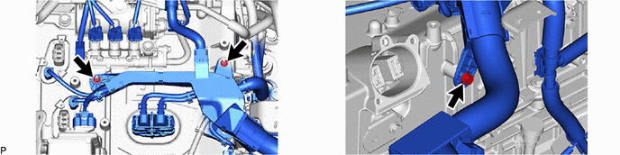
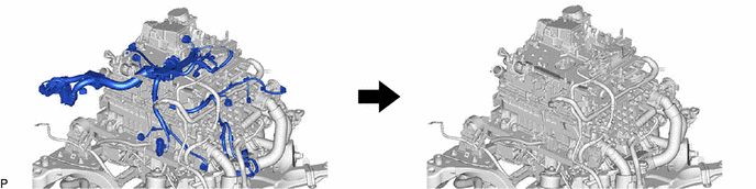
G90A1
134.REMOVE NO. 1 FC INVERTER COOLING HOSE SUB-ASSEMBLY
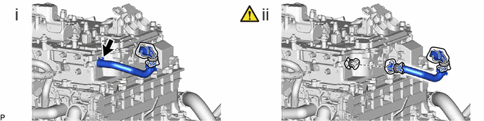
Slide the clip, remove the No. 1 FC inverter cooling hose sub-assembly.
Cover the connection of the No. 1 FC inverter cooling hose sub-assembly and FC converter assembly with plastic bags to prevent the foreign matter.
23C13
135.REMOVE NO. 2 HYDROGEN PUMP BRACKET

G91C5
136.REMOVE NO. 5 FC INVERTER COOLING HOSE
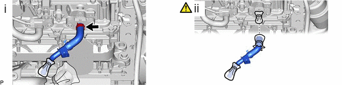
Slide the clip, remove the No. 5 FC inverter cooling hose.
Cover the connection of the No. 5 FC inverter cooling hose and FC converter assembly with plastic bags to prevent the foreign matter.
165H6
137.REMOVE NO. 6 FC RADIATOR PIPE
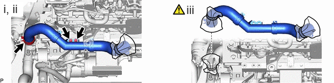
Slide the clip, disconnect the No. 12 FC radiator hose.
Remove the 2 bolts and No. 6 FC radiator pipe.
Cover the connection of the No. 12 FC radiator hose and No. 6 FC radiator pipe with plastic bags to prevent the foreign matter.
16611C
138.REMOVE RADIATOR RESERVE TANK BRACKET

17A40A
139.REMOVE FC AIR COMPRESSOR BREATHER ASSEMBLY

16573D
140.REMOVE NO. 3 FC RADIATOR HOSE
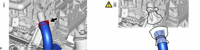
Slide the clip, disconnect the No. 3 FC radiator hose.
Cover the connection of the No. 3 FC radiator hose and FC stack air and water inlet with plastic bags to prevent the foreign matter.
23B13
141.REMOVE NO. 3 HYDROGEN TUBE
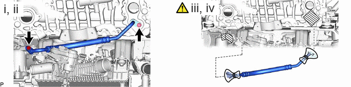
Remove the 2 bolts and No. 3 hydrogen tube.
Remove the 2 O-rings from the No. 3 hydrogen tube.
Cover the connection of the No. 3 hydrogen tube with plastic bags to prevent the foreign matter.
Protect the openings of the FC stack assembly and hydrogen recirculation pump assembly with protective tape (non-residue type) to prevent the entry of foreign matter or water.
87121W
142.REMOVE WATER PUMP BRACKET

G9A76
143.REMOVE FC CONVERTER SUPPORT PLATE

G9A2E
144.REMOVE FC CONVERTER SPACER

165F7
145.REMOVE NO. 7 RADIATOR HOSE BRACKET

165F5
146.REMOVE NO. 5 RADIATOR HOSE BRACKET

G9A25
147.REMOVE FC CONVERTER POWER OUTLET BRACKET

87452Q
148.REMOVE NO. 1 HEATER BRACKET

16A1BA
149.REMOVE NO. 1 FC COOLING WATER PUMP CABLE BRACKET

16A1BB
150.REMOVE NO. 2 FC COOLING WATER PUMP CABLE BRACKET

G9A84B
151.REMOVE NO. 3 FC JUNCTION CABLE BRACKET

G9A84
152.REMOVE NO. 1 FC JUNCTION CABLE BRACKET

16A1AA
153.REMOVE NO. 1 FC WATER AND HYDROGEN PUMP CABLE BRACKET

16A1AB
154.REMOVE NO. 2 FC WATER AND HYDROGEN PUMP CABLE BRACKET

16A1AC
155.REMOVE NO. 3 FC WATER AND HYDROGEN PUMP CABLE BRACKET

17AA3A
156.REMOVE NO. 1 FC AIR COMPRESSOR CABLE BRACKET

17AA3D
157.REMOVE NO. 4 FC AIR COMPRESSOR CABLE BRACKET

158.REMOVE WIRE HARNESS CLAMP BRACKET
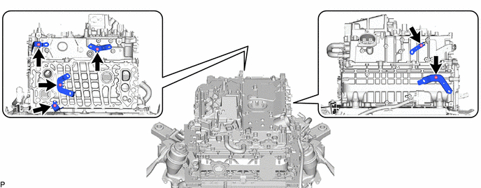
G4151
159.REMOVE HYDROGEN DETECTOR
|
|
Click here()
|
17B21
160.REMOVE FC STACK AIR INLET HOSE
|
|
Click here()
|
17D10
161.REMOVE FC STACK AIR OUTLET HOSE ASSEMBLY
|
|
Click here()
|
162. PERFORM ELECTRICAL CHARGE SELF-DISCHARGE (WHEN FORCED ELECTRICAL CHARGE DISCHARGE NOT POSSIBLE)
|
|
|
Go to Perform Electrical Charge Self-discharge (When Forced Electrical Charge Discharge Not Possible)
Click hereEngine / Hybrid System>FC CONTROL>FC STACK>Electrical Charge Self-discharge Work
17C10
163.REMOVE FC AIR PRESSURE REGULATOR ASSEMBLY (AIR SEALING VALVE)
|
|
Click here()
|
23A30
164.REMOVE HYDROGEN SUPPLY PRESSURE REGULATOR ASSEMBLY
|
|
Click here()
|
23B11
165.REMOVE NO. 1 HYDROGEN TUBE
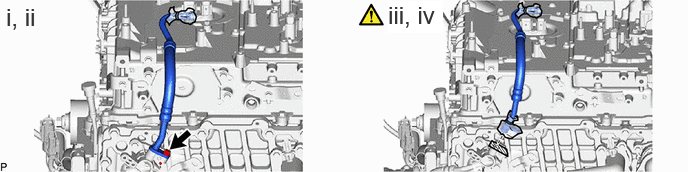
Remove the bolt and No. 1 hydrogen tube.
Remove the O-ring from the No. 1 hydrogen tube.
Cover the connection of the No. 1 hydrogen tube with plastic bags to prevent the foreign matter.
Protect the openings of the FC stack hydrogen inlet with protective tape (non-residue type) to prevent the entry of foreign matter or water.
23B12
166.REMOVE NO. 2 HYDROGEN TUBE
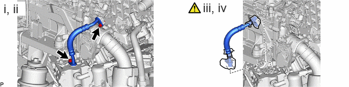
Remove the 2 bolts and No. 2 hydrogen tube.
Remove the 2 O-rings from the No. 2 hydrogen tube.
Cover the connection of the No. 2 hydrogen tube with plastic bags to prevent the foreign matter.
Protect the openings of the FC stack hydrogen inlet and hydrogen recirculation pump assembly with protective tape (non-residue type) to prevent the entry of foreign matter or water.
17C10
167.REMOVE FC AIR PRESSURE REGULATOR ASSEMBLY (AIR PRESSURE REGULATING VALVE)
|
|
Click here()
|
77B0D
168.REMOVE NO. 1 HYDROGEN SUPPLY TUBE SUB-ASSEMBLY

169.REMOVE FC CONVERTER WITH FC STACK ASSEMBLY
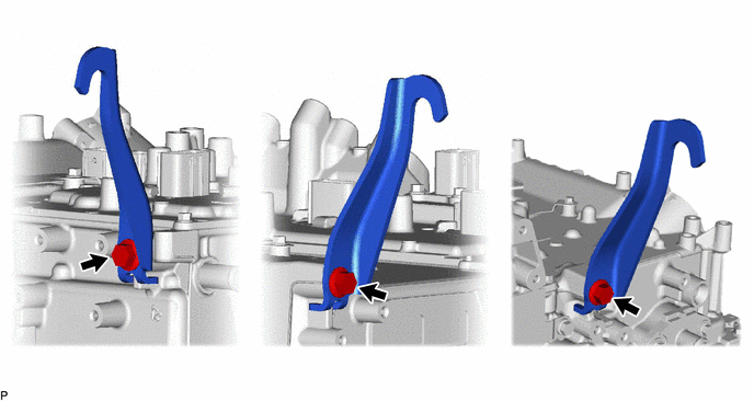
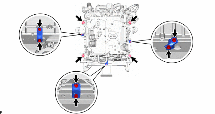
Install the engine hanger with the 3 bolts as shown in the illustration.
- Torque:
- 32 N*m (326 kgf*cm, 24 ft.*lbf)
- HINT:
Engine Hanger 12282-28010 Bolt 91552-K1025
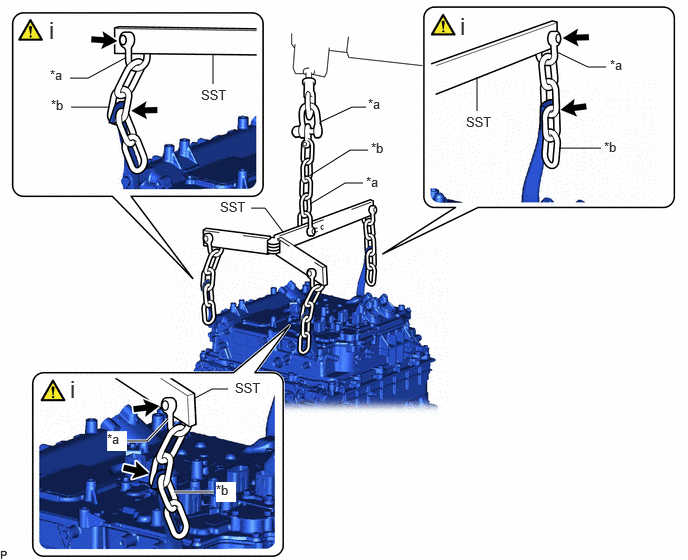
| *a | Shackle (A) (09943-01020) | *b | Chain (09941-01010) |
Set up SST and the chain block as shown in the illustration.
- SST
- 09940-78010 (09941-01010, 09943-01020)
- NOTICE:
- ·
Set up SST and the chain block so that the FC stack assembly with FC converter is level.
·Do not hoist the FC stack assembly with FC converter from points other than those shown in the illustration.
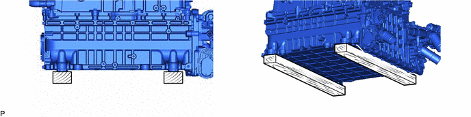
Put wooden blocks on the work table and place the FC converter with FC stack assembly on them.
G9A28
170.REMOVE FRONT FC CONVERTER SERVICE HOLE COVER

1A19A
171.REMOVE NO. 1 FC STACK CASE PLUG

G9A74
172.REMOVE FC CONVERTER VENT COVER

173.CLEAN FC CONVERTER WITH FC STACK ASSEMBLY
Using a cloth, remove dirt and dust from the FC stack assembly with FC converter surface and around the bolts.
174. BOLT FALLING PREVENTION WORK (FRONT SIDE (POSITIVE TERMINAL))
|
|
|
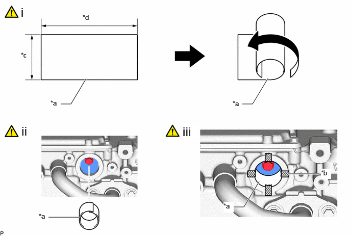
| *a | Paper | *b | Tape |
| *c | Approximately 33 mm | *d | Approximately 110 mm |
Prepare paper of the size shown in the illustration, and roll up the paper so that it overlaps.
Insert the rolled up paper into the FC converter assembly.
Firmly secure the inserted paper to the FC converter assembly with tape.
- NOTICE:
- ·
Be sure to perform this work, because it may not be possible to retrieve the bolt if it falls inside the FC stack assembly.
·Store the rolled up paper because it will be used again during installation.
1A100
175.REMOVE FC STACK ASSEMBLY
| *a | Shackle (A) (09943-01020) | *b | Chain (09941-01010) |
Set up SST and the chain block as shown in the illustration.
- SST
- 09940-78010 (09941-01010, 09943-01020)
- NOTICE:
- ·
Set up SST and the chain block so that the FC stack assembly with FC converter is level.
·Do not hoist the FC stack assembly with FC converter from points other than those shown in the illustration.
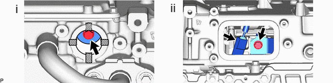
Remove the bolt.
Disconnect the connector and remove the bolt.
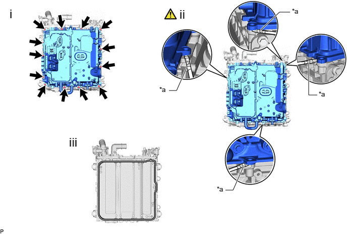
| *a | Protective tape | - | - |
Remove the 13 bolts.
Using a screwdriver with its tip wrapped with protective tape, pry the points shown in the illustration and remove the FC stack assembly.
- NOTICE:
-
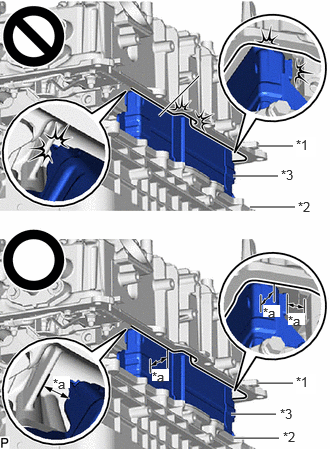 1.656,1.208 2.073,0.792 true 2.688,1.521 3.052,1.521 true 2.427,1.833 2.896,1.833 true 2.604,2.156 3.073,2.156 true 2.688,3.99 3.052,3.99 true 2.406,4.313 2.875,4.313 true 2.438,4.563 2.906,4.563 true 3.083,1.427 3.292,1.635 0.208,0.208 10 true *1 3.104,2.073 3.313,2.271 0.208,0.198 10 false *2 2.927,1.74 3.146,1.938 0.219,0.198 10 false *3 0.552,3.917 0.729,4.042 0.177,0.125 10 true *a 3,3.26 3.177,3.385 0.177,0.125 10 true *a 2.74,3.177 2.917,3.302 0.177,0.125 10 true *a 1.583,3.844 1.76,3.969 0.177,0.125 10 true *a 2.948,4.469 3.156,4.667 0.208,0.198 10 false *2 2.917,4.229 3.135,4.427 0.219,0.198 10 false *3 3.083,3.896 3.292,4.104 0.208,0.208 10 true *1
*1 FC Converter Assembly *2 FC Stack Assembly *3 FC Stack Voltage Sensor *a Gap
- ·
Remove the FC stack assembly carefully in a perpendicular orientation while making sure not to subject it to any impacts, because there is an FC stack voltage sensor on the FC stack assembly side, and the gap between the FC stack voltage sensor and FC converter assembly is small.
·Do not damage the contact surfaces of the FC stack assembly and FC converter assembly.
Remove the gasket from the FC stack assembly.
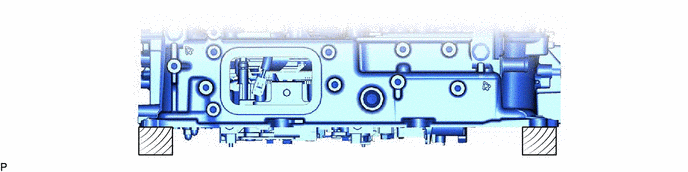
Put wooden blocks on the work table and place the FC converter assembly on them.
- NOTICE:
-
Use wooden blocks so that the protruding parts on the lower portion of the FC converter assembly does not make contact with the work table.
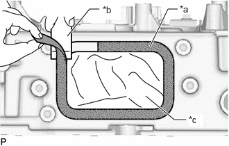
| *a | Remaining Double-sided Tape |
| *b | Scraper Made of Resin |
| *c | Protect with Cloth, etc. |
Clean FC converter vent cover installation surface
Protect the FC converter assembly with a cloth, etc., to prevent dirt or foreign matter from entering it, as shown in the illustration.
Use a scraper made of resin to remove the remaining double-sided tape from the FC converter vent cover installation surface.
- NOTICE:
-
Never remove using a screwdriver or scraper made of metal, etc., because doing so may cause damage that results in problems such as poor adhesion.
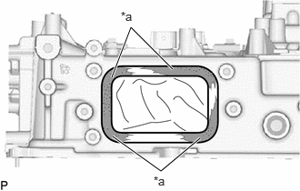
| *a | Remaining Double-sided Tape |
Clean and degrease the installation surface of the FC converter vent cover using non-residue solvent and brake cleaner.
- NOTICE:
- ·
Installing the FC converter vent cover with some double-sided tape remaining may cause poor adhesion. Remove the double-sided tape completely.
·Never remove using a screwdriver or scraper made of metal, etc., because doing so may cause damage that results in problems such as poor adhesion.
- HINT:
-
After removing the tape with a scraper made of resin, spraying non-residue solvent and brake cleaner onto the tape remaining on the adhesional surface and rubbing it with a cloth, etc., makes it easy to remove the tape.