TIRE PRESSURE MONITORING TIRE PRESSURE WARNING SYSTEM Tire Pressure Warning Light Circuit
DESCRIPTION
for ECE-R64 Type and FMVSS138 Type:
If the tire pressure warning ECU and receiver detects any problems, the tire pressure warning light blinks for 1 minute then illuminates, and tire pressure monitoring is disabled at the same time. At this time, the ECU stores a DTC in memory.
for GB26149 Type:
If the tire pressure warning ECU and receiver detects any problems, the tire pressure warning light blinks, and tire pressure monitoring is disabled at the same time. At this time, the ECU stores a DTC in memory.
The tire pressure warning ECU and receiver sends the tire pressure warning light illumination request signal to the main body ECU (multiplex network body ECU) via a direct line. The main body ECU (multiplex network body ECU) then sends the signal to the combination meter assembly via CAN communication.
WIRING DIAGRAM
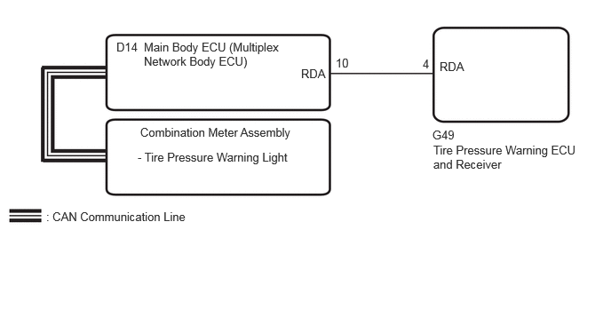
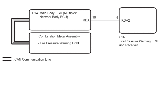
CAUTION / NOTICE / HINT
- NOTICE:
- ·
When replacing the tire pressure warning ECU and receiver, first use the GTS to record all of the current IDs and registered tires with transmitters (4 or 5 tires) of the tire pressure warning valve and transmitter registered to the tire pressure warning ECU and receiver.
·It is necessary to perform initialization Suspension>TIRE PRESSURE MONITORING>TIRE PRESSURE WARNING SYSTEM>INITIALIZATION after registrationSuspension>TIRE PRESSURE MONITORING>TIRE PRESSURE WARNING SYSTEM>REGISTRATION of the transmitter IDs into the tire pressure warning ECU and receiver if the ECU has been replaced.
PROCEDURE
Check if CAN communication system DTCs are output.
Click herePower Source / Network>NETWORKING>CAN COMMUNICATION SYSTEM>DIAGNOSIS SYSTEM
- Result:
Result Proceed to DTCs are not output A DTCs are output B
A
B
Click herePower Source / Network>NETWORKING>CAN COMMUNICATION SYSTEM>HOW TO PROCEED WITH TROUBLESHOOTING
- Result:
Result Proceed to excluding JPD20R-CEDSSW (w/ Panic Switch) A for JPD20R-CEDSSW (w/ Panic Switch) B
A
B
Inspect the combination meter assembly.
Click hereVehicle Interior>METER / GAUGE / DISPLAY>METER / GAUGE SYSTEM>HOW TO PROCEED WITH TROUBLESHOOTING
- Result:
Proceed to OK NG
OK
Click hereSuspension>TIRE PRESSURE MONITORING>TIRE PRESSURE WARNING RECEIVER (for Luggage Compartment)>REMOVAL
NG
Click hereVehicle Interior>METER / GAUGE / DISPLAY>METER / GAUGE SYSTEM>HOW TO PROCEED WITH TROUBLESHOOTING
Inspect the combination meter assembly.
Click hereVehicle Interior>METER / GAUGE / DISPLAY>METER / GAUGE SYSTEM>HOW TO PROCEED WITH TROUBLESHOOTING
- Result:
Proceed to OK NG
OK
Click hereSuspension>TIRE PRESSURE MONITORING>TIRE PRESSURE WARNING RECEIVER (for Quarter Pillar)>REMOVAL
NG
Click hereVehicle Interior>METER / GAUGE / DISPLAY>METER / GAUGE SYSTEM>HOW TO PROCEED WITH TROUBLESHOOTING