FC CONTROL CONVERTER ASSEMBLY DISASSEMBLY
CAUTION / NOTICE / HINT
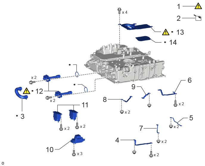
| Procedure | Part Name Code | 
|

|

|
|
|---|---|---|---|---|---|
| 1 | SUPPORT FC CONVERTER ASSEMBLY | G9A10 | ( ) |
- | - |
| 2 | DRAIN COOLANT (TOYOTA GENUINE FC STACK COOLANT (Pre-mixed)) | - | - | ()
|
- |
| 3 | FC CONVERTER COOLING HOSE | G9A41 | - | - | - |
| 4 | NO. 6 FC CONVERTER BUS-BAR PLATE | - | - | - | - |
| 5 | NO. 5 FC CONVERTER BUS-BAR PLATE | - | - | - | - |
| 6 | NO. 4 FC CONVERTER BUS-BAR PLATE | - | - | - | - |
| 7 | NO. 3 FC CONVERTER BUS-BAR PLATE | - | - | - | - |
| 8 | NO. 2 FC CONVERTER BUS-BAR PLATE | - | - | - | - |
| 9 | NO. 1 FC CONVERTER BUS-BAR PLATE | - | - | - | - |
| 10 | FC PRECHARGE JUNCTION ASSEMBLY | G9A60 | - | - | - |
| 11 | FC STACK MAIN RELAY | 1A511 | - | - | - |
| 12 | FC CONVERTER COOLING PIPE | G9A43 | ()
|
- | - |
| 13 | FC CONVERTER SIGNAL CONNECTOR COVER | G9A13 | ()
|
- | - |
| 14 | NO. 1 FC STACK CASE PLUG | 1A19A | - | - | - |
| ● | Non-reusable part | - | - |
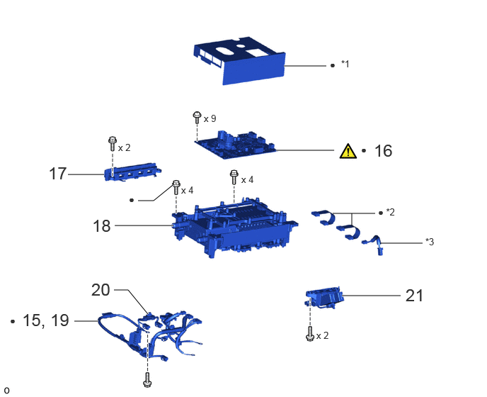
| Procedure | Part Name Code |
|
|
|
|
|---|---|---|---|---|---|
| 15 | DISCONNECT NO. 1 FC CONVERTER WIRE | G9A1C | - | - | - |
| 16 | FCDC CONVERTER CONTROL ECU BOARD SUB-ASSEMBLY | F160A | ()
|
- | - |
| 17 | FC CONVERTER CURRENT SENSOR | G9A1K | - | - | - |
| 18 | FC CONVERTER POWER MODULE TRANSISTOR (IPM) | F17C6 | - | - | - |
| 19 | REMOVE NO. 1 FC CONVERTER WIRE | G9A1C | - | - | - |
| 20 | NO. 2 FC CONVERTER WIRE | G9A1D | - | - | - |
| 21 | FC CONVERTER POWER OUTLET TERMINAL SUB-ASSEMBLY | G9A02 | - | - | - |
| *1 | FC CONVERTER SHEET | *2 | ECU WIRE SUB-ASSEMBLY |
| *3 | NO. 3 FC CONVERTER WIRE | - | - |
| ● | Non-reusable part | - | - |
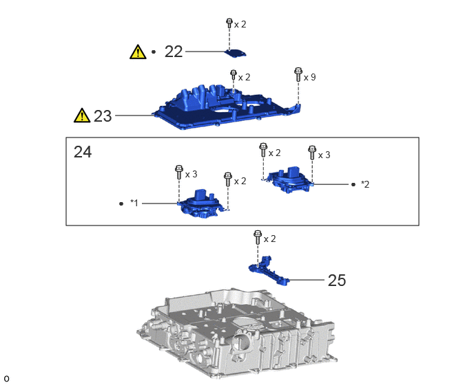
| Procedure | Part Name Code |
|
|
|
|
|---|---|---|---|---|---|
| 22 | REAR FC CONVERTER SERVICE HOLE COVER | G9A29 | ()
|
- | - |
| 23 | FC INVERTER INPUT JUNCTION COVER | G9A72 | ()
|
- | - |
| 24 | FC COOLING WATER PUMP INVERTER ASSEMBLY AND FC HYDROGEN PUMP INVERTER ASSEMBLY | - | - | - | - |
| 25 | FC WATER AND HYDROGEN PUMP INVERTER TERMINAL | G9A83 | - | - | - |
| *1 | FC COOLING WATER PUMP INVERTER ASSEMBLY | *2 | FC HYDROGEN PUMP INVERTER ASSEMBLY |
| ● | Non-reusable part | - | - |
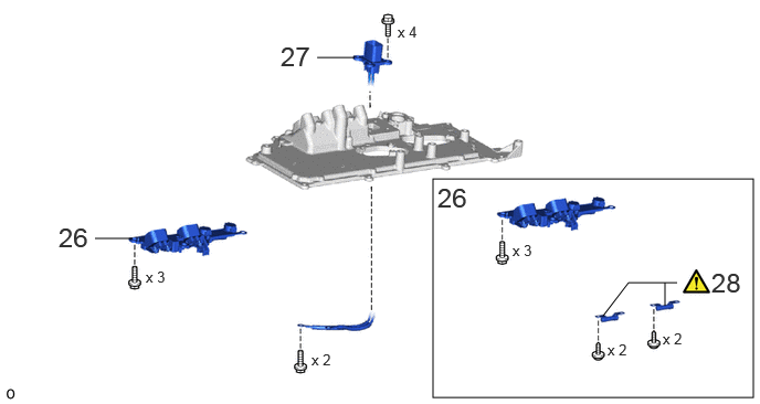
| Procedure | Part Name Code |
|
|
|
|
|---|---|---|---|---|---|
| 26 | FC INVERTER INPUT TERMINAL | G9A71 | - | - | - |
| 27 | AIR CONDITIONING COMPRESSOR CABLE | G9A7A | - | - | - |
| 28 | HIGH VOLTAGE FUSE | G9A71B | ()
|
- | - |
PROCEDURE

 G9A10
1.SUPPORT FC CONVERTER ASSEMBLY
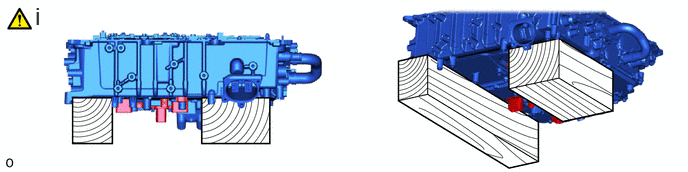
Using wooden blocks, etc. support the FC converter assembly horizontally at the areas shown in the illustration.
- NOTICE:
-
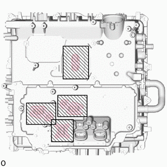 0,0 0,0 false

Areas that must not be used for support
-
Do not support from the areas indicated in the illustration (connectors).
2.DRAIN COOLANT (TOYOTA GENUINE FC STACK COOLANT (Pre-mixed))
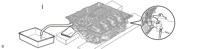
Blow air in from the areas shown in the illustration and continue to perform air blowing until coolant no longer comes out from inside the FC converter assembly.
G9A41
3.REMOVE FC CONVERTER COOLING HOSE

4.REMOVE NO. 6 FC CONVERTER BUS-BAR PLATE

5.REMOVE NO. 5 FC CONVERTER BUS-BAR PLATE

6.REMOVE NO. 4 FC CONVERTER BUS-BAR PLATE

7.REMOVE NO. 3 FC CONVERTER BUS-BAR PLATE

8.REMOVE NO. 2 FC CONVERTER BUS-BAR PLATE

9.REMOVE NO. 1 FC CONVERTER BUS-BAR PLATE

G9A60
10.REMOVE FC PRECHARGE JUNCTION ASSEMBLY

1A511
11.REMOVE FC STACK MAIN RELAY

G9A43
12.REMOVE FC CONVERTER COOLING PIPE
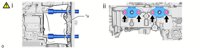
| *a | Cloth, etc. | - | - |
Set a cloth, etc. inside the FC converter assembly as shown in the illustration.
- HINT:
-
After removing each FC converter cooling pipe from the FC converter power module transistor (IPM) connector area, place a cloth, etc. to prevent remaining coolant (Toyota genuine FC stack coolant (Pre-mixed) from running and dirtying the FC converter case sub-assembly. If coolant (Toyota genuine FC stack coolant (Pre-mixed) becomes adhered to the FC converter case sub-assembly, etc., be sure to wipe it off completely.
Remove the 4 bolts, 2 FC converter cooling pipes and 2 gaskets.
G9A13
13.REMOVE FC CONVERTER SIGNAL CONNECTOR COVER
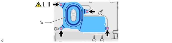
| *a | FIPG | - | - |
Remove the 4 bolts.
FIPG is applied between the FC converter signal connector cover and FC converter case sub-assembly. Use a scraper made of resin to remove it.
- NOTICE:
-
Never use a screwdriver or scraper made of metal, etc., because doing so may cause damage or poor adhesion.
1A19A
14.REMOVE NO. 1 FC STACK CASE PLUG

G9A1C
15.DISCONNECT NO. 1 FC CONVERTER WIRE

F160A
16.REMOVE FCDC CONVERTER CONTROL ECU BOARD SUB-ASSEMBLY
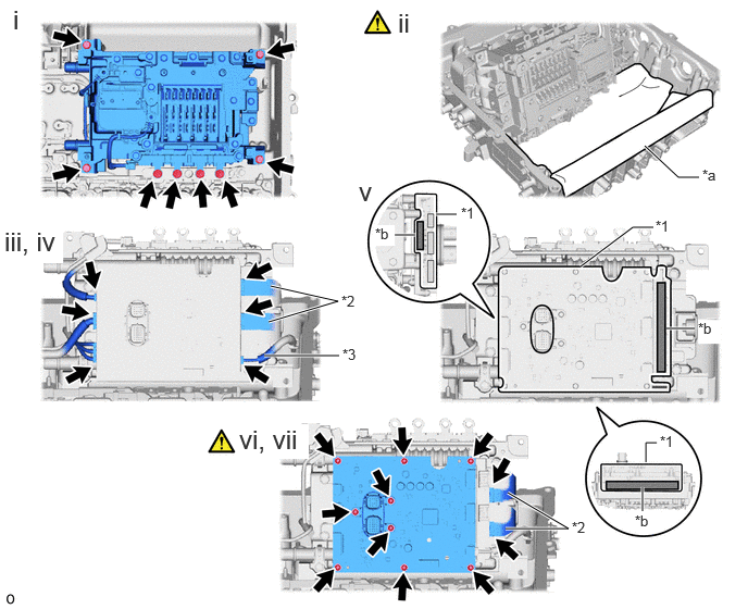
| *1 | FC Converter Sheet | *2 | ECU Wire Sub-assembly |
| *3 | NO. 3 FC Converter Wire | - | - |
| *a | Cloth, etc. | *b | Double-side Tape |
Remove the 8 bolts.
Set a cloth, etc. inside the FC converter assembly as shown in the illustration.
- HINT:
-
When placing the FC converter power module transistor (IPM) against the FC converter case sub-assembly, place a cloth, etc. so that the FC converter power module transistor (IPM) and case are not damaged.
Disconnect the 5 connecters.
- NOTICE:
-
Do not apply excessive force to the FCDC converter control ECU board sub-assembly connector.
Disconnect the connector and remove the No. 3 FC converter wire.
- NOTICE:
-
Do not apply excessive force to the FCDC converter control ECU board sub-assembly connector.
Double-sided tape is applied at the area shown in the illustration. Remove the tape and FC converter sheet.
Disconnect the 2 connectors and remove the 2 ECU wire sub-assemblies.
- NOTICE:
-
Do not apply excessive force to the FCDC converter control ECU board sub-assembly connector.
Using the magnetic screwdriver of the FC converter power module transistor kit, remove the 9 screws and FCDC converter control ECU board sub-assembly.
G9A1K
17.REMOVE FC CONVERTER CURRENT SENSOR

F17C6
18.REMOVE FC CONVERTER POWER MODULE TRANSISTOR (IPM)
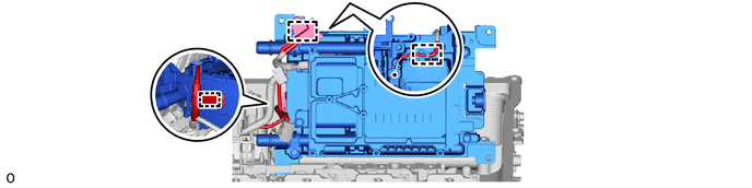
G9A1C
19.REMOVE NO. 1 FC CONVERTER WIRE

G9A1D
20.REMOVE NO. 2 FC CONVERTER WIRE

G9A02
21.REMOVE FC CONVERTER POWER OUTLET TERMINAL SUB-ASSEMBLY

G9A29
22.REMOVE REAR FC CONVERTER SERVICE HOLE COVER
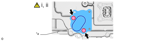
| *a | FIPG | - | - |
Remove the 2 bolts.
FIPG is applied between the FC converter service hole cover and FC inverter input junction cover. Use a scraper made of resin to remove it.
- NOTICE:
-
Never use a screwdriver or scraper made of metal, etc., because doing so may cause damage or poor adhesion.
G9A72
23.REMOVE FC INVERTER INPUT JUNCTION COVER

Remove the 11 bolts.
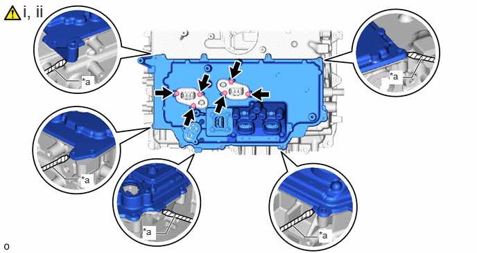
| *a | Protective Tape | - | - |

|
Included bolts (Pump Inverter Kit) | - | - |
Using a screwdriver with its tip wrapped with protective tape, pry the areas shown in the illustration and remove the FIPG from the outside edge of the FC inverter input junction cover.
Install the 6 included bolts (pump inverter kit) to the FC inverter input junction cover, and remove the FC inverter input junction cover.
24.REMOVE FC COOLING WATER PUMP INVERTER ASSEMBLY AND FC HYDROGEN PUMP INVERTER ASSEMBLY

G9A83
25.REMOVE FC WATER AND HYDROGEN PUMP INVERTER TERMINAL

G9A71
26.REMOVE FC INVERTER INPUT TERMINAL

G9A7A
27.REMOVE AIR CONDITIONING COMPRESSOR CABLE

G9A71B
28.REMOVE HIGH VOLTAGE FUSE
|
|
|