FC CONTROL CONVERTER ASSEMBLY REASSEMBLY
CAUTION / NOTICE / HINT
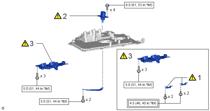
| Procedure | Part Name Code | 
|

|

|
|
|---|---|---|---|---|---|
| 1 | HIGH VOLTAGE FUSE | G9A71B | ( ) |
- | - |
| 2 | AIR CONDITIONING COMPRESSOR CABLE | G9A7A | ()
|
- | - |
| 3 | FC INVERTER INPUT TERMINAL | G9A71 | ()
|
- | - |

|
Tightening torque for "Major areas involving basic vehicle performance such as moving/turning/stopping": N*m(kgf*cm, ft.*lbf) | 
|
N*m (kgf*cm, ft.*lbf): Specified torque |
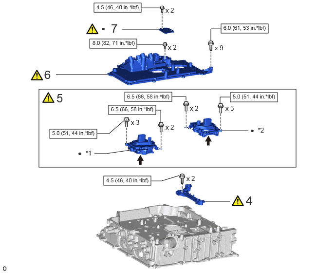
| Procedure | Part Name Code |
|
|
|
|
|---|---|---|---|---|---|
| 4 | FC WATER AND HYDROGEN PUMP INVERTER TERMINAL | G9A83 | ()
|
- | - |
| 5 | FC COOLING WATER PUMP INVERTER ASSEMBLY AND FC HYDROGEN PUMP INVERTER ASSEMBLY | - | ()
|
- | - |
| 6 | FC INVERTER INPUT JUNCTION COVER | G9A72 | ()
|
- | - |
| 7 | REAR FC CONVERTER SERVICE HOLE COVER | G9A29 | ()
|
- | - |
| *1 | FC COOLING WATER PUMP INVERTER ASSEMBLY | *2 | FC HYDROGEN PUMP INVERTER ASSEMBLY |
|
|
N*m (kgf*cm, ft.*lbf): Specified torque | ● | Non-reusable part |

|
THERMAL GREASE X-23-7887-4 | - | - |
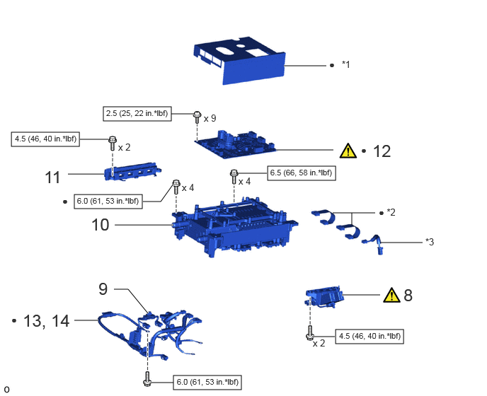
| Procedure | Part Name Code |
|
|
|
|
|---|---|---|---|---|---|
| 8 | FC CONVERTER POWER OUTLET TERMINAL SUB-ASSEMBLY | G9A02 | ()
|
- | - |
| 9 | NO. 2 FC CONVERTER WIRE | G9A1D | - | - | - |
| 10 | FC CONVERTER POWER MODULE TRANSISTOR (IPM) | F17C6 | - | - | - |
| 11 | FC CONVERTER CURRENT SENSOR | G9A1K | - | - | - |
| 12 | FCDC CONVERTER CONTROL ECU BOARD SUB-ASSEMBLY | F160A | ()
|
- | - |
| 13 | INSTALL NO. 1 FC CONVERTER WIRE | G9A1C | ()
|
- | - |
| 14 | CONNECT NO. 1 FC CONVERTER WIRE | G9A1C | - | - | - |
| *1 | FC CONVERTER SHEET | *2 | ECU WIRE SUB-ASSEMBLY |
| *3 | NO. 3 FC CONVERTER WIRE | - | - |
|
|
N*m (kgf*cm, ft.*lbf): Specified torque | ● | Non-reusable part |
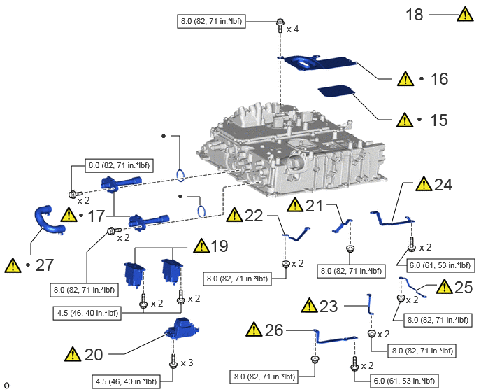
| Procedure | Part Name Code |
|
|
|
|
|---|---|---|---|---|---|
| 15 | NO. 1 FC STACK CASE PLUG | 1A19A | ()
|
- | - |
| 16 | FC CONVERTER SIGNAL CONNECTOR COVER | G9A13 | ()
|
- | - |
| 17 | FC CONVERTER COOLING PIPE | G9A43 | ()
|
- | - |
| 18 | LEAK CHECK (INSPECT FOR COOLANT (TOYOTA GENUINE FC STACK COOLANT (Pre-mixed)) LEAK) | - | ()
|
- | - |
| 19 | FC STACK MAIN RELAY | 1A511 | ()
|
- | - |
| 20 | FC PRECHARGE JUNCTION ASSEMBLY | G9A60 | ()
|
- | - |
| 21 | NO. 1 FC CONVERTER BUS-BAR PLATE | - | ()
|
- | - |
| 22 | NO. 2 FC CONVERTER BUS-BAR PLATE | - | ()
|
- | - |
| 23 | NO. 3 FC CONVERTER BUS-BAR PLATE | - | ()
|
- | - |
| 24 | NO. 4 FC CONVERTER BUS-BAR PLATE | - | ()
|
- | - |
| 25 | NO. 5 FC CONVERTER BUS-BAR PLATE | - | ()
|
- | - |
| 26 | NO. 6 FC CONVERTER BUS-BAR PLATE | - | ()
|
- | - |
| 27 | FC CONVERTER COOLING HOSE | G9A41 | ()
|
- | - |
|
|
N*m (kgf*cm, ft.*lbf): Specified torque | ● | Non-reusable part |
PROCEDURE

 G9A71B
1.INSTALL HIGH VOLTAGE FUSE
|
|
|

Using a T20 "TORX" socket wrench, temporarily install the 2 high voltage fuses with the 4 bolts.
Tighten the 4 bolts in the order shown in the illustration.
- Torque:
- 4.5 N*m (46 kgf*cm, 40 in.*lbf)
G9A7A
2.INSTALL AIR CONDITIONING COMPRESSOR CABLE

Temporarily install the air conditioning compressor cable with the 4 bolts.
Tighten the 4 bolts in the order shown in the illustration.
- Torque:
- 6.0 N*m (61 kgf*cm, 53 in.*lbf)
G9A71
3.INSTALL FC INVERTER INPUT TERMINAL
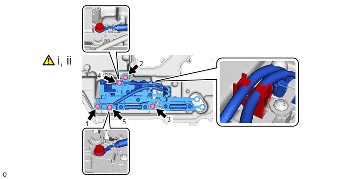
Temporarily install the FC inverter input terminal with the 5 bolts.
- HINT:
-
Install the harness as shown in the illustration.
Tighten the 5 bolts in the order shown in the illustration.
- Torque:
- 5.0 N*m (51 kgf*cm, 44 in.*lbf)
G9A83
4.INSTALL FC WATER AND HYDROGEN PUMP INVERTER TERMINAL
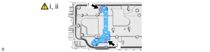
Temporarily install the FC water and hydrogen pump inverter terminal with the 2 bolts.
Tighten the 2 bolts in the order shown in the illustration.
- Torque:
- 4.5 N*m (46 kgf*cm, 40 in.*lbf)
5.INSTALL FC COOLING WATER PUMP INVERTER ASSEMBLY AND FC HYDROGEN PUMP INVERTER ASSEMBLY
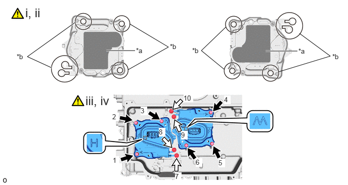
| *a | Apply grease here | *b | Do not apply grease here |
|
|
Bolt A | 
|
Bolt B |

|
THERMAL GREASE X-23-7887-4 | - | - |
Clean grease from the FC cooling water pump inverter assembly and FC hydrogen pump inverter assembly installation areas on the FC converter case sub-assembly.
- NOTICE:
-
Clean and degrease the installation surface using non-residue solvent and brake cleaner.
Apply Toyota genuine thermal grease X-23-7887-4 to a new FC cooling water pump inverter assembly and new FC hydrogen pump inverter assembly, and set them to the FC converter case sub-assembly.
- NOTICE:
- ·
Do not allow grease on the 4 bus bar locations and 6 installation seat locations on the FC cooling water pump inverter assembly and FC hydrogen pump inverter assembly.
·Do not allow heat dissipating grease on other parts, etc. before seating the FC converter case sub-assembly.
·Do not reuse the FC cooling water pump inverter assembly and FC hydrogen pump inverter assembly.
Temporarily install the FC cooling water pump inverter assembly and FC hydrogen pump inverter assembly with the 10 bolts.
| Item | Length |
|---|---|
| A | 16 mm (0.630 in.) |
| B | 12 mm (0.472 in.) |
Tighten the 10 bolts in the order shown in the illustration.
- Torque:
- for bolt A : 5.0 N*m (51 kgf*cm, 44 in.*lbf)
- for bolt B : 6.5 N*m (66 kgf*cm, 58 in.*lbf)
G9A72
6.INSTALL FC INVERTER INPUT JUNCTION COVER
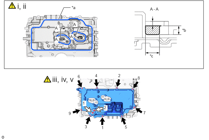
| *a | Seal Packing Diameter: 2.0 to 3.5 mm (0.0787 to 0.138 in.)
Seal Packing Diameter: 2.0 to 6.5 mm (0.0787 to 0.256 in.) (Start/End Point Only) |
*b | Groove Width: 4.0 mm (0.157 in.) |
| *c | Groove Width: 6.1 to 6.5 mm (0.240 to 0.256 in.) | - | - |
|
|
Bolt A |
|
Bolt B |
Before applying seal packing, cleanly remove any old sealant sticking to the part to be sealed.
Apply seal packing black to the areas shown in the illustration.
- NOTICE:
- ·
Check and clean bolts and bolt holes.
·Clean and degrease the installation surface using non-residue solvent and brake cleaner.
·Install the part within 3 minutes and finish all tightening within 15 minutes after applying seal packing.
Temporarily install the FC inverter input junction cover with the 9 bolts labeled A.
| Item | Length |
|---|---|
| A | 16 mm (0.630 in.) |
Tighten the 9 bolts labeled A in the order shown in the illustration.
- Torque:
- for bolt A : 6.0 N*m (61 kgf*cm, 53 in.*lbf)
Install the 2 bolts labeled B in the order shown in the illustration.
- Torque:
- for bolt B : 8.0 N*m (82 kgf*cm, 71 in.*lbf)
| Item | Length |
|---|---|
| B | 12 mm (0.472 in.) |
G9A29
7.INSTALL REAR FC CONVERTER SERVICE HOLE COVER
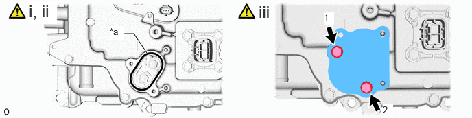
| *a | Seal Packing Diameter: 2.0 to 3.5 mm (0.0787 to 0.138 in.)
Seal Packing Diameter: 2.0 to 6.5 mm (0.0787 to 0.256 in.) (Start/End Point Only) |
- | - |
Before applying seal packing, cleanly remove any old sealant sticking to the part to be sealed.
Apply seal packing black to the areas shown in the illustration.
- NOTICE:
- ·
Check and clean bolts and bolt holes.
·Clean and degrease the installation surface using non-residue solvent and brake cleaner.
·Install the part within 3 minutes and finish all tightening within 15 minutes after applying seal packing.
Install a new rear FC converter service hole cover with the 2 bolts in the order shown in the illustration.
- Torque:
- 4.5 N*m (46 kgf*cm, 40 in.*lbf)
G9A02
8.INSTALL FC CONVERTER POWER OUTLET TERMINAL SUB-ASSEMBLY

Temporarily install the FC converter power outlet terminal sub-assembly with the 2 bolts.
Tighten the 2 bolts in the order shown in the illustration.
- Torque:
- 4.5 N*m (46 kgf*cm, 40 in.*lbf)
G9A1D
9.INSTALL NO. 2 FC CONVERTER WIRE

F17C6
10.INSTALL FC CONVERTER POWER MODULE TRANSISTOR (IPM)

G9A1K
11.INSTALL FC CONVERTER CURRENT SENSOR

- Torque:
- 4.5 N*m (46 kgf*cm, 40 in.*lbf)
F160A
12.INSTALL FCDC CONVERTER CONTROL ECU BOARD SUB-ASSEMBLY
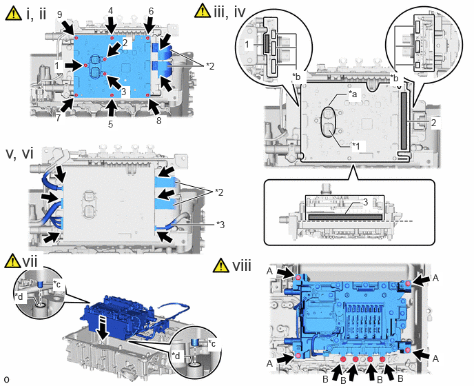
| *1 | Low Voltage Connector | *2 | ECU Wire Sub-assembly |
| *3 | NO. 3 FC Converter Wire | - | - |
| *a | FC converter sheet hole | *b | Connector Hole |
| *c | Knock Pin | *d | Pin Hole |
Using the magnetic screwdriver of the FC converter power module transistor kit, install a new FCDC converter control ECU board sub-assembly with the 9 screws in the order shown in the illustration.
- Torque:
- 2.5 N*m (25 kgf*cm, 22 in.*lbf)
- NOTICE:
-
Do not drop screws on the FCDC converter control ECU board sub-assembly.
Connect the 2 connectors and install the 2 new ECU wire sub-assemblies.
Insert and position the low voltage connector in the hole on the FC converter sheet as shown in the illustration.
Remove the peeling paper on a new FC converter sheet while making sure not to touch the adhesional surface.
Attach the new FC converter sheet to the FC converter power module transistor (IPM) as shown in the illustration.
- NOTICE:
- ·
Do not touch the adhesive part of the double-sided tape.
·Check that there is no foreign matter or other substances that could affect adhesiveness on the double-sided tape application surface.
·Attach so that the connector holes are not blocked.
·Do not to apply excessive force to the FCDC converter control ECU board sub-assembly when attaching it.
- HINT:
-
It is recommended to attach in the order shown in the illustration.
Connect the connector and install the No. 3 FC converter wire.
Connect the 5 connectors.
- NOTICE:
-
Do not apply excessive force to the FCDC converter control ECU board sub-assembly connector.
Align the knock pin on the FC converter power module transistor (IPM) with the pinhole on the case, and set the FC converter power module transistor (IPM).
Install the FC converter power module transistor (IPM) with the 4 new bolts (A) and 4 bolts (B).
- Torque:
- for bolt A : 6.0 N*m (61 kgf*cm, 53 in.*lbf)
- for bolt B : 6.5 N*m (66 kgf*cm, 58 in.*lbf)
- NOTICE:
- ·
Clean the hole for bolt A and the bolt A installation area.
·Tighten the 8 bolts in the order of (A) and (B).
G9A1C
13.INSTALL NO. 1 FC CONVERTER WIRE

- Torque:
- 6.0 N*m (61 kgf*cm, 53 in.*lbf)
G9A1C
14.CONNECT NO. 1 FC CONVERTER WIRE

1A19A
15.INSTALL NO. 1 FC STACK CASE PLUG
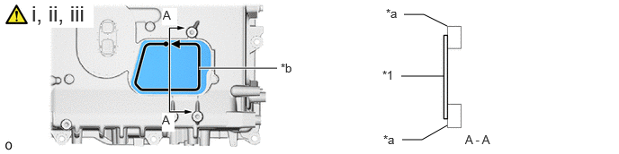
| *1 | No. 1 FC Stack Case Plug | - | - |
| *a | FC Converter Case Sub-assembly Edge | *b | Check installation area |
Remove the peeling paper on a new No. 1 FC stack case plug while making sure not to touch the adhesional surface.
Install the No. 1 FC stack case plug to the FC converter case sub-assembly.
- NOTICE:
-
Clean and degrease the installation surface of the No. 1 FC stack case plug.
Trace once around the installation area of the No. 1 FC stack case plug and check that it is securely installed.
G9A13
16.INSTALL FC CONVERTER SIGNAL CONNECTOR COVER
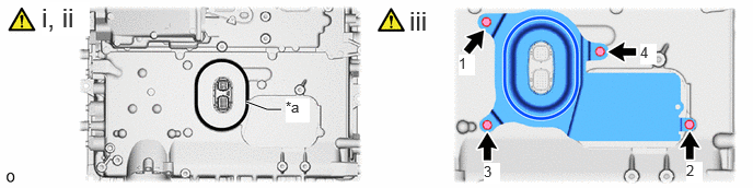
| *a | Seal Packing Diameter: 2.0 to 3.5 mm (0.0787 to 0.138 in.)
Seal Packing Diameter: 2.0 to 6.5 mm (0.0787 to 0.256 in.) (Start/End Point Only) |
- | - |
Before applying seal packing, cleanly remove any old sealant sticking to the part to be sealed.
Apply seal packing black to the areas shown in the illustration.
- NOTICE:
- ·
Check and clean bolts and bolt holes.
·Clean and degrease the installation surface using non-residue solvent and brake cleaner.
·Install the part within 3 minutes and finish all tightening within 15 minutes after applying seal packing.
Install the FC converter signal connector cover to the FC converter case sub-assembly with the 4 bolts in the order shown in the illustration.
- Torque:
- 8.0 N*m (82 kgf*cm, 71 in.*lbf)
G9A43
17.INSTALL FC CONVERTER COOLING PIPE
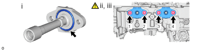
Install 2 new gaskets to the 2 new FC converter cooling pipes.
- NOTICE:
-
Do not reuse the FC converter cooling pipe.
Temporarily install the 2 FC converter cooling pipes with the 4 bolts.
Tighten the 4 bolts in the order shown in the illustration.
- Torque:
- 8.0 N*m (82 kgf*cm, 71 in.*lbf)
18. LEAK CHECK (INSPECT FOR COOLANT (TOYOTA GENUINE FC STACK COOLANT (Pre-mixed)) LEAK)
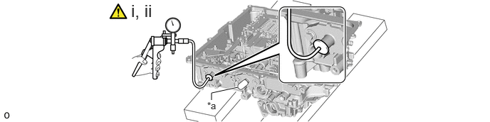
| *a | Rubber Plug | - | - |
Install the rubber plug at the point shown in the illustration.
Using a vacuum pump, apply a vacuum (50 kPa (375 mmHg, 14.8 in.Hg)).
- Standard:
No decrease in pressure for 30 seconds
- NOTICE:
-
If the pressure decreases, check carefully for air leaks from the connection between the vacuum pump and coolant pipe. If there are no leaks, remove the FC converter cooling pipe and check the installation condition of the gasket. Also check the O-ring on the FC converter cooling pipe.
1A511
19.INSTALL FC STACK MAIN RELAY
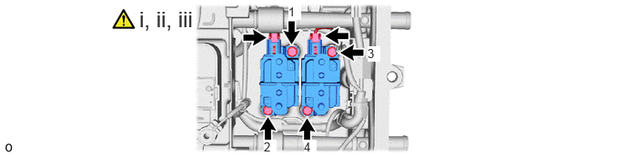
Temporarily install the 2 FC stack main relaies with the 4 bolts.
Tighten the 4 bolts in the order shown in the illustration.
- Torque:
- 4.5 N*m (46 kgf*cm, 40 in.*lbf)
Connect the 2 connectors.
G9A60
20.INSTALL FC PRECHARGE JUNCTION ASSEMBLY
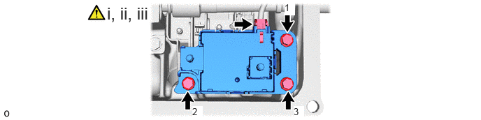
Temporarily install the FC precharge junction assembly with the 3 bolts.
Tighten the 3 bolts in the order shown in the illustration.
- Torque:
- 4.5 N*m (46 kgf*cm, 40 in.*lbf)
Connect the connector.
21.INSTALL NO. 1 FC CONVERTER BUS-BAR PLATE
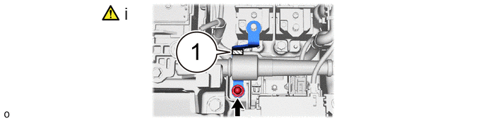
Install the No. 1 FC converter bus-bar plate with the nut.
- Torque:
- 8.0 N*m (82 kgf*cm, 71 in.*lbf)
22.INSTALL NO. 2 FC CONVERTER BUS-BAR PLATE

Temporarily install the No. 2 FC converter bus-bar plate with the 2 nuts.
Tighten the 2 nuts in the order shown in the illustration.
- Torque:
- 8.0 N*m (82 kgf*cm, 71 in.*lbf)
23.INSTALL NO. 3 FC CONVERTER BUS-BAR PLATE

Temporarily install the No. 3 FC converter bus-bar plate with the 2 nuts.
Tighten the 2 nuts in the order shown in the illustration.
- Torque:
- 8.0 N*m (82 kgf*cm, 71 in.*lbf)
24.INSTALL NO. 4 FC CONVERTER BUS-BAR PLATE
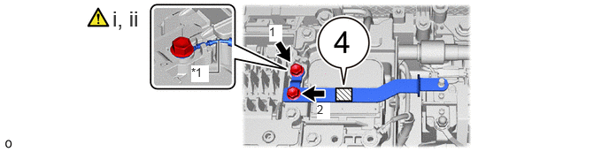
| *1 | No. 1 FC Converter Wire | - | - |
Temporarily install the No. 4 FC converter bus-bar plate and No. 1 FC converter wire with the 2 bolts.
Tighten the 2 bolts in the order shown in the illustration.
- Torque:
- 6.0 N*m (61 kgf*cm, 53 in.*lbf)
25.INSTALL NO. 5 FC CONVERTER BUS-BAR PLATE

Temporarily install the No. 5 FC converter bus-bar plate with the 2 nuts.
Tighten the 2 nuts in the order shown in the illustration.
- Torque:
- 8.0 N*m (82 kgf*cm, 71 in.*lbf)
26.INSTALL NO. 6 FC CONVERTER BUS-BAR PLATE
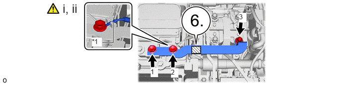
| *1 | No. 1 FC Converter Wire | - | - |
Temporarily install the No. 6 FC converter bus-bar plate and No. 1 FC converter wire with the 2 bolts and nut.
Tighten the 2 bolts and nut in the order shown in the illustration.
- Torque:
- for bolt : 6.0 N*m (61 kgf*cm, 53 in.*lbf)
- for nut : 8.0 N*m (82 kgf*cm, 71 in.*lbf)
G9A41
27.INSTALL FC CONVERTER COOLING HOSE
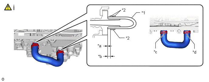
| *1 | FC Converter Cooling Hose | *2 | Hose Clip |
| *a | Hose Installation Area (2.0 mm (0.0787 in.) or less) | *b | Hose Clip Installation Area (2.0 to 7.0 mm (0.0787 to 0.276 in.)) |
| *c | Paint Mark (Yellow) | *d | Paint Mark (White) |
Install a new FC converter cooling hose as shown in the illustration.