FC CONTROL FC STACK VOLTAGE SENSOR INSTALLATION
CAUTION / NOTICE / HINT
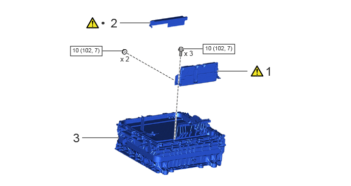
| Procedure | Part Name Code | 
|

|

|
|
|---|---|---|---|---|---|
| 1 | FC STACK VOLTAGE SENSOR | 1A671 | ( ) |
- | - |
| 2 | FC CONVERTER SHEET | G9A51 | ()
|
- | - |
| 3 | FC STACK ASSEMBLY | - | - | - | - |

|
N*m (kgf*cm, ft.*lbf): Specified torque | ● | Non-reusable part |
PROCEDURE

 1A671
1.INSTALL FC STACK VOLTAGE SENSOR
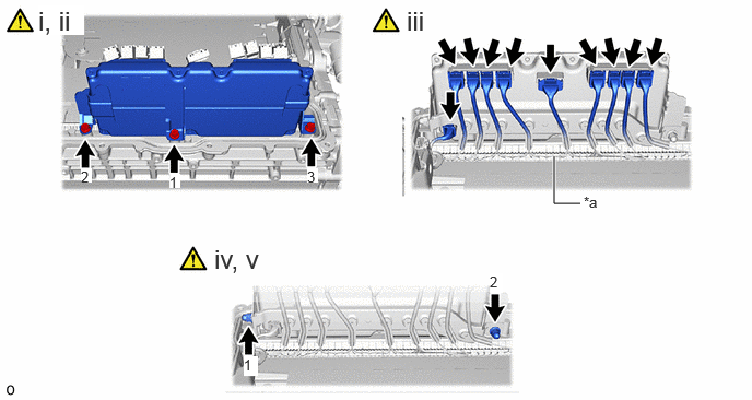
| *a | Connectors on FC Stack Side | - | - |
Temporarily install the 3 bolts.
- NOTICE:
-
The FC stack voltage sensor is not self-supported. Temporarily install while supporting the FC stack voltage sensor.
Tighten the 3 bolts in the order shown in the illustration, and install the FC stack voltage sensor.
- Torque:
- 10 N*m (102 kgf*cm, 7 ft.*lbf)
Connect the 10 connectors to the FC stack voltage sensor.
- NOTICE:
-
Check that the connectors on the FC stack side are not lifted.
Temporarily install the 2 nuts.
Tighten the 2 nuts in the order shown in the illustration, and install the FC stack wire harness protector.
- Torque:
- 10 N*m (102 kgf*cm, 7 ft.*lbf)
- NOTICE:
- ·
Check that the connectors on the cell side are not lifted.
·If they are lifted, connect the connector deeply.
G9A51
2.INSTALL FC CONVERTER SHEET
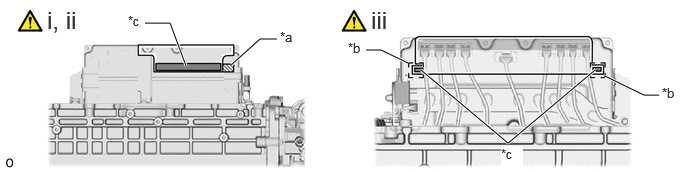
| *a | Peeling Paper | *b | Marking |
| *c | Double-sided Tape | - | - |
Remove the peeling paper on a new FC converter sheet while making sure not to touch the adhesional surface.
Attach the FC converter sheet to the FC stack voltage sensor as shown in the illustration.
- NOTICE:
-
Check that there is no foreign matter or other substances that could affect adhesiveness on the double-sided tape application surface.
Attach the FC converter sheet within the marking area of the FC stack voltage sensor as shown in the illustration.
- NOTICE:
-
Check that there is no foreign matter or other substances that could affect adhesiveness on the double-sided tape application surface.
1A100
3.INSTALL FC STACK ASSEMBLY