 |
- The emission control systems components
- The power train control components (which affect vehicle emissions)
- The computer itself
SFI SYSTEM > DIAGNOSIS SYSTEM |
| DESCRIPTION |
|
| NORMAL MODE AND CHECK MODE |
| 2 TRIP DETECTION LOGIC |
| FREEZE FRAME DATA |
| DATA LINK CONNECTOR 3 (DLC3) |
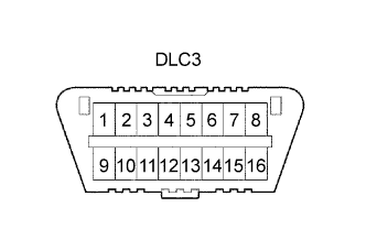 |
| Symbols | Terminal No. | Names | Reference terminal | Results | Condition |
| SIL | 7 | Bus "+" line | 5 - Signal ground | Pulse generation | During transmission |
| CG | 4 | Chassis ground | Body ground | 1 Ω or less | Always |
| SG | 5 | Signal ground | Body ground | 1 Ω or less | Always |
| BAT | 16 | Battery positive | Body ground | 9 to 14 V | Always |
| CANH | 6 | CAN "High" line | 14 - CANL | 54 to 69 Ω | Power switch OFF |
| CANH | 6 | CAN "High" line | Battery positive | 6 kΩ or higher | Power switch OFF |
| CANH | 6 | CAN "High" line | 4 - CG | 200 Ω or higher | Power switch OFF |
| CANL | 14 | CAN "Low" line | Battery positive | 6 kΩ or higher | Power switch OFF |
| CANL | 14 | CAN "Low" line | 4 - CG | 200 Ω or higher | Power switch OFF |
| BATTERY VOLTAGE |
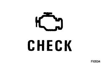
| MIL (Malfunction Indicator Lamp) |
The MIL is illuminated when the power switch is first turned ON (the engine is not running).
When the HV main system is activated (READY ON), the MIL should turn off. If the MIL illuminates again, the diagnosis system has detected a malfunction or abnormality in the system.
| ALL READINESS |