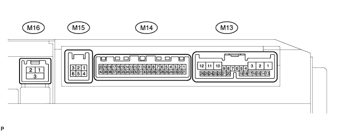
NAVIGATION SYSTEM > TERMINALS OF ECU |
| CHECK MULTI-DISPLAY |
Disconnect the M13 display connector.
Measure the resistance and voltage of the wire harness side connector.
| Symbols (Terminal No.) | Wiring Color | Terminal Description | Condition | Specified Condition |
| GND1 (M13-1) - Body ground | BR - Body ground | Ground | Always | Below 1 Ω |
| ACC (M13-2) - Body ground | GR - Body ground | ACC power supply | Power switch ON (ACC) | 10 to 14 V |
| IG (M13-10) - Body ground | B - Body ground | IG power supply | Power switch ON (IG) | 10 to 14 V |
| +B1 (M13-3) - Body ground | Y - Body ground | Battery power supply | Always | 10 to 14 V |
Reconnect the M13 display connector.
Measure the voltage of the connector.
| Symbols (Terminal No.) | Wiring Color | Terminal Description | Condition | Specified Condition |
| TSW- (M14-8) - SGND (M14-1) | BR - BR | Shielded ground | Always | Below 1 V |
| SGND (M14-21) - Body ground | Shielded - Body ground | Shielded ground | Always | Below 1 V |
| MCO+ (M14-22) - Body ground | R - Body ground | Microphone voice signal | See "Microphone & Voice Recognition Check" mode | - |
| MCO- (M14-23) - Body ground | G - Body ground | Microphone voice signal | See "Microphone & Voice Recognition Check" mode | - |
| TX+ (M14-13) - Body ground | W - Body ground | AVC-LAN communication signal | Power switch ON (ACC) | 2 to 3 V |
| TX- (M14-14) - Body ground | P - Body ground | AVC-LAN communication signal | Power switch ON (ACC) | 2 to 3 V |
| TX2+ (M13-18) - Body ground | P - Body ground | AVC-LAN communication signal | Power switch ON (ACC) | 2 to 3 V |
| TX2- (M13-19) - Body ground | W - Body ground | AVC-LAN communication signal | Power switch ON (ACC) | 2 to 3 V |
| TX1+ (M13-4) - Body ground | B - Body ground | AVC-LAN communication signal | Power switch ON (ACC) | 2 to 3 V |
| TX1- (M13-5) - Body ground | W - Body ground | AVC-LAN communication signal | Power switch ON (ACC) | 2 to 3 V |
| TX4- (M15-6) - Body ground | P - Body ground | AVC-LAN communication signal | Power switch ON (ACC) | 2 to 3 V |
| TX4+ (M15-3) - Body ground | W - Body ground | AVC-LAN communication signal | Power switch ON (ACC) | 2 to 3 V |
| SLD (M14-24) - Body ground | Shielded - Body ground | Shielded ground | Always | Below 1 V |
| IVO- (M14-26) - Body ground | R - Body ground | Voice guidance signal | Voice guidance is provided | Waveform synchronized with sound is output |
| IVO+ (M14-25) - Body ground | G - Body ground | Voice guidance signal | Voice guidance is provided | Waveform synchronized with sound is output |
| SPD (M13-20) - Body ground | V - Body ground | Speed signal | See "Vehicle Signal Check" mode | - |
| TC (M13-7) - Body ground | P - Body ground | Diagnosis ON signal | Power switch ON (IG) | 9 to 14 V |
| DR (M13-17) - Body ground | B - Body ground | Illumination signal | Light control switch TAIL or HEAD | 2 to 3 V |
| MIN+ (M14-2) - Body ground | G - Body ground | Microphone voice signal | See "Microphone & Voice Recognition Check" mode | - |
| MIN- (M14-3) - Body ground | R - Body ground | Microphone voice signal | See "Microphone & Voice Recognition Check" mode | - |
| MACC (M14-4) - Body ground | BR - Body ground | Microphone amplifier power supply | Power switch ON (IG) | 5 V |
| GVIF (M16-1) - Body ground | B - Body ground | Digital image signal | Multi-display ON | Pulse generation |
| IVI- (M14-6) - Body ground | W - Body ground | Voice guidance signal | Voice guidance is provided | Waveform synchronized with sound is output |
| IVI+ (M14-5) - Body ground | B - Body ground | Voice guidance signal | Voice guidance is provided | Waveform synchronized with sound is output |
| CHECK NAVIGATION ECU |
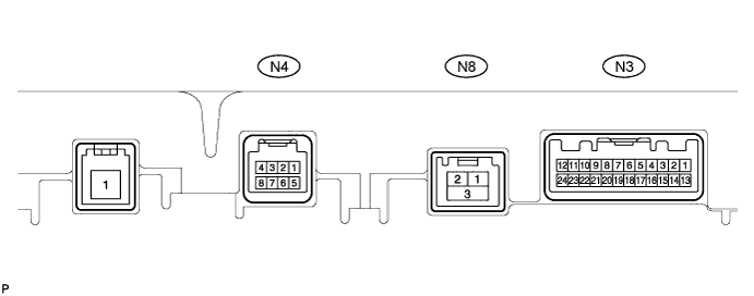
Disconnect the N3 ECU connector.
Measure the resistance and voltage of the wire harness side connector.
| Symbols (Terminal No.) | Wiring Color | Terminal Description | Condition | Specified Condition |
| +B (N3-1) - Body ground | SB - Body ground | Battery power supply | Always | 10 to 14 V |
| ACC (N3-13) - Body ground | GR - Body ground | ACC power supply | Power switch ON (ACC) | 10 to 14 V |
| GND1 (N3-15) -Body ground | W-B - Body ground | Ground | Always | Below 1 Ω |
Reconnect the N3 ECU connector.
Measure the voltage of the connector.
| Symbols (Terminal No.) | Wiring Color | Terminal Description | Condition | Specified Condition |
| SPD (N3-4) - Body ground | V - Body ground | Speed signal | See "Vehicle Signal Check" mode | - |
| REV (N3-20) - Body ground | R - Body ground | Reverse signal | See "Vehicle Signal Check" mode | - |
| MIC+ (N4-3) - Body ground | R - Body ground | Microphone voice signal | See "Microphone & Voice Recognition Check" mode | - |
| MIC- (N4-5) - Body ground | G - Body ground | Microphone voice signal | See "Microphone & Voice Recognition Check" mode | - |
| TX- (N3-18) - Body ground | P - Body ground | AVC-LAN communication signal | Power switch ON (ACC) | 2 to 3 V |
| TX+ (N3-19) - Body ground | W - Body ground | AVC-LAN communication signal | Power switch ON (ACC) | 2 to 3 V |
| GVIF (N8-1) - Body ground | B - Body ground | Digital image signal | Multi-display ON | Pulse generation |
| SLD1 (N3-7) - Body ground | Shielded - Body ground | Shielded ground | Always | Below 1 V |
| VOI- (N3-8) - Body ground | W - Body ground | Voice guidance signal | Voice guidance is provided | Waveform synchronized with sound is output |
| VOI+ (N3-9) - Body ground | B - Body ground | Voice guidance signal | Voice guidance is provided | Waveform synchronized with sound is output |
| CHECK RADIO RECEIVER (Click here) |
| CHECK STEREO COMPONENT AMPLIFIER (Click here) |
| CHECK TELEVISION CAMERA (Click here) (w/ Rear View Monitor System) |
| CHECK GATEWAY ECU (Click here) |